
Method and apparatus for a control communication channel in a packet-forwarding device

a packet-forwarding device and communication channel technology, applied in the field of network device architecture and operation, can solve the problems of wasting valuable processor resources, adding to coordination complexity, and huge differences in time constraints associated with various control functions, so as to improve reliability, reduce congestion, and improve scalability

Active Publication Date: 2007-07-17
EXTREME NETWORKS INC
View PDF3 Cites 34 Cited by
  • Summary
  • Abstract
  • Description
  • Claims
  • Application Information

AI Technical Summary

Benefits of technology

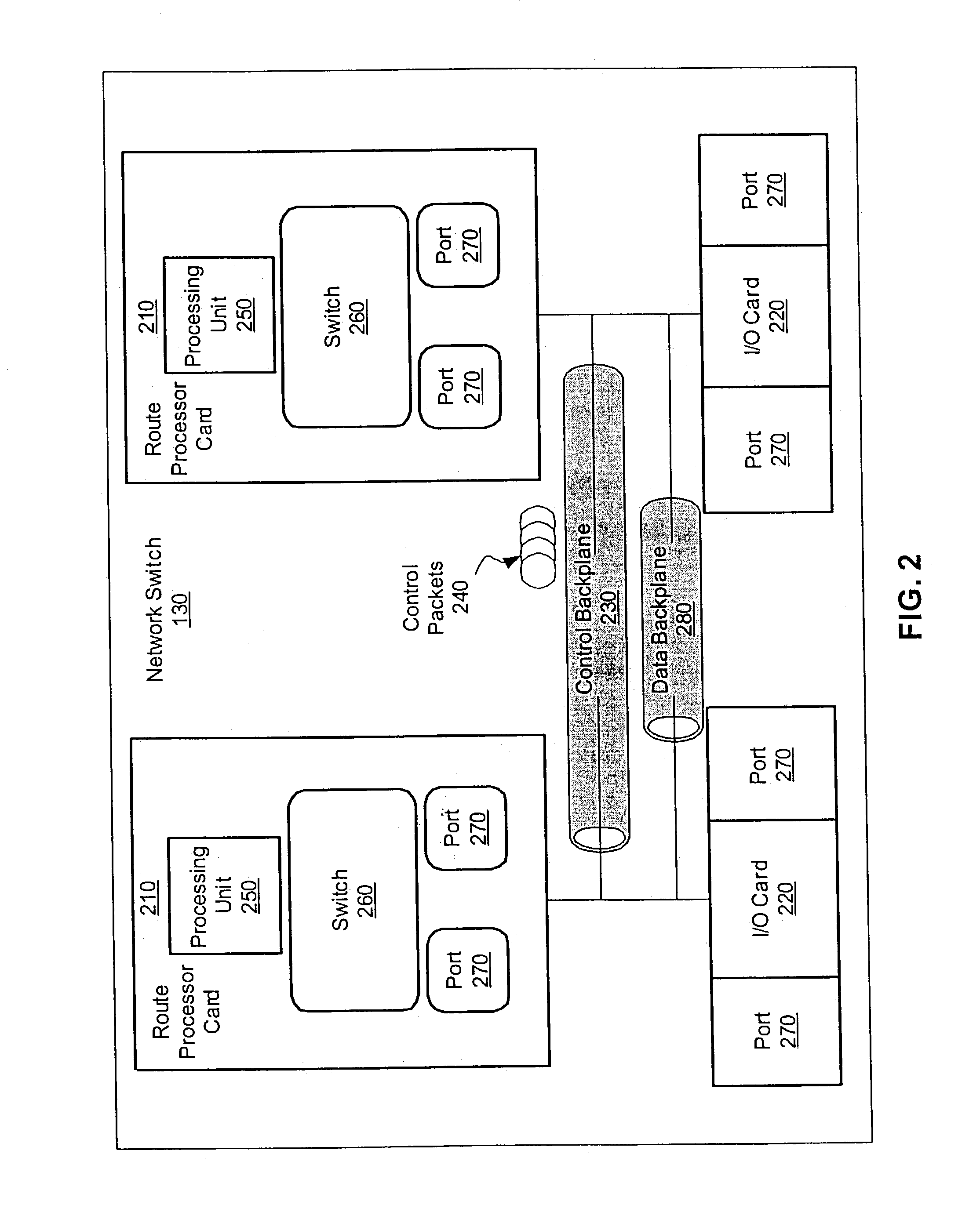
[0009]A method is provided for a control backplane system in which a separate control backplane is used as a communication channel for transmitting control information in a packet-forwarding device. Exemplary control information includes management, configuration, security, accounting, debugging, external network management, and background routing processes. Among other advantages, the use of a control backplane to deliver the control information improves scalability by reducing the congestion and improves reliability by making the packet-forwarding device less susceptible to a single point of failure.
[0011]According to one aspect of the invention, the control backplane system advantageously improves performance of the packet-forwarding device by using a high-speed protocol to deliver the control information. The control backplane system packetizes the control information into control packets in accordance with the high-speed protocol and further supports concurrent control sessions in the communication channel in which the control packets are transmitted simultaneously between components within the packet-forwarding device, as well as between clients or other devices associated with the packet-forwarding device. According to one aspect of the invention, the control backplane system generates the control packets from external control packets originating from external network devices connected to the packet-forwarding device.

Problems solved by technology

The occasional control function received from an external device, such as a remote terminal or server, adds to the coordination complexity, as control functions received on the data plane must be converted for transmission across the control plane.
Because of the irregular nature of many control functions, there is a tremendous difference in the time constraints associated with various control functions.
These irregularities create overhead that drains valuable resources from the processor unit.
Unfortunately, these shared buses, which share the communication channel between multiple functions, easily become congested under modern switching demands, especially if the bus bandwidth doesn't match the aggregate data rate of the ports and processor unit Input / Output (I / O), thus limiting the performance of the system.
Unfortunately, continuing this pattern of development with regards to shared backplanes is impractical for several reasons.
One reason is that a shared bus reduces the overall reliability of the packet-forwarding device.
As control functions must pass across the shared bus, it becomes a single point of failure that potentially shuts down the entire packet-forwarding device.
Even worse, a failed shared bus may introduce erratic undetectable errors, which alter the data being transmitted through the packet-forwarding device causing the data to be corrupted.
Another reason is low scalability of shared bus architectures.
The scalability or transfer-capacity of a shared bus is limited by several factors including electrical loading, the number of connectors that a signal encounters, and the reflections from the end of unterminated lines.
In addition, scalability of the shared bus is often limited by congestion on the shared bus.
Specifically, the bandwidth of the bus is shared among all the attached devices so that any contention between attached devices leads to additional delay for control information being sent across the shared control bus.
If the rate of control information exceeds the bus bandwidth for a sustained period, buffers risk overflow-errors and loss of data.

Method used


Image

  • Method and apparatus for a control communication channel in a packet-forwarding device
  • Method and apparatus for a control communication channel in a packet-forwarding device
  • Method and apparatus for a control communication channel in a packet-forwarding device

Examples


Embodiment Construction

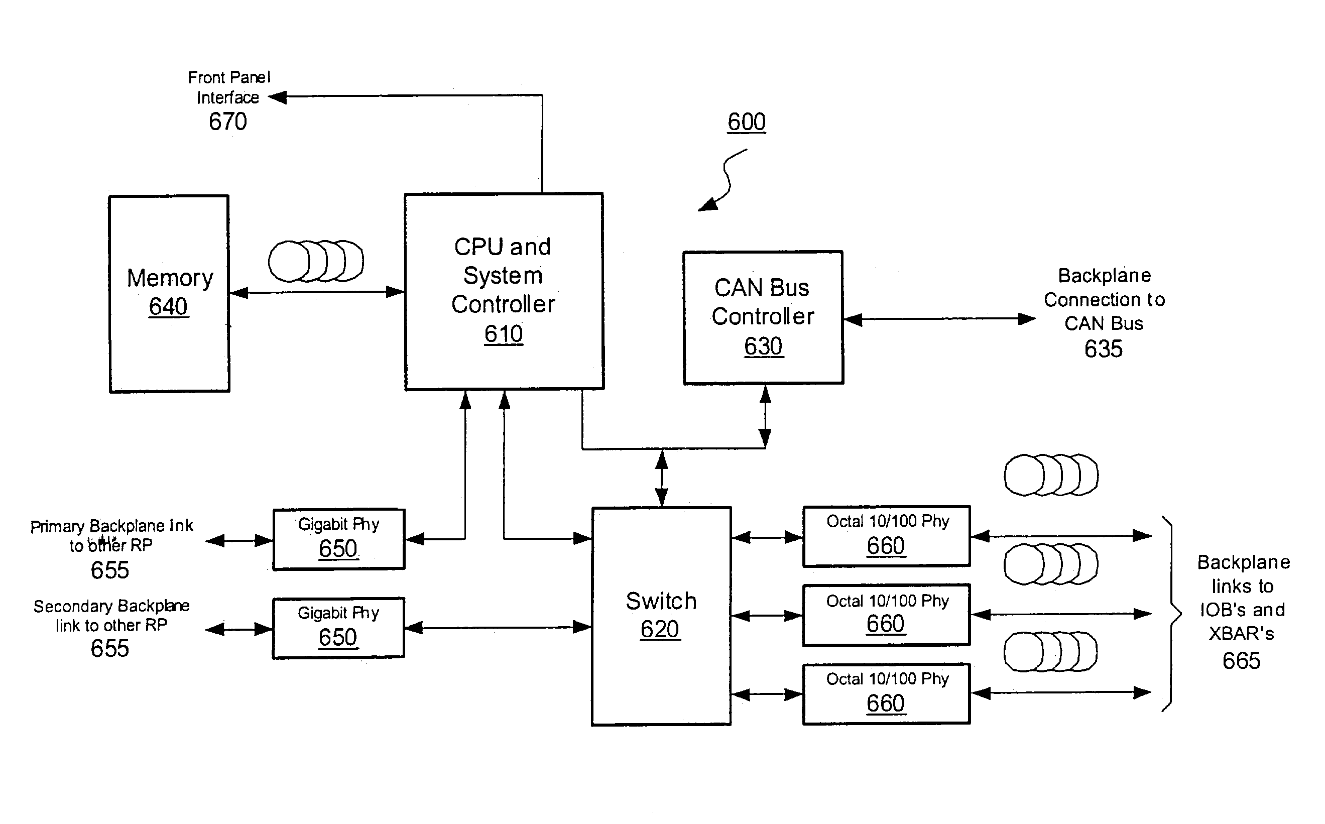
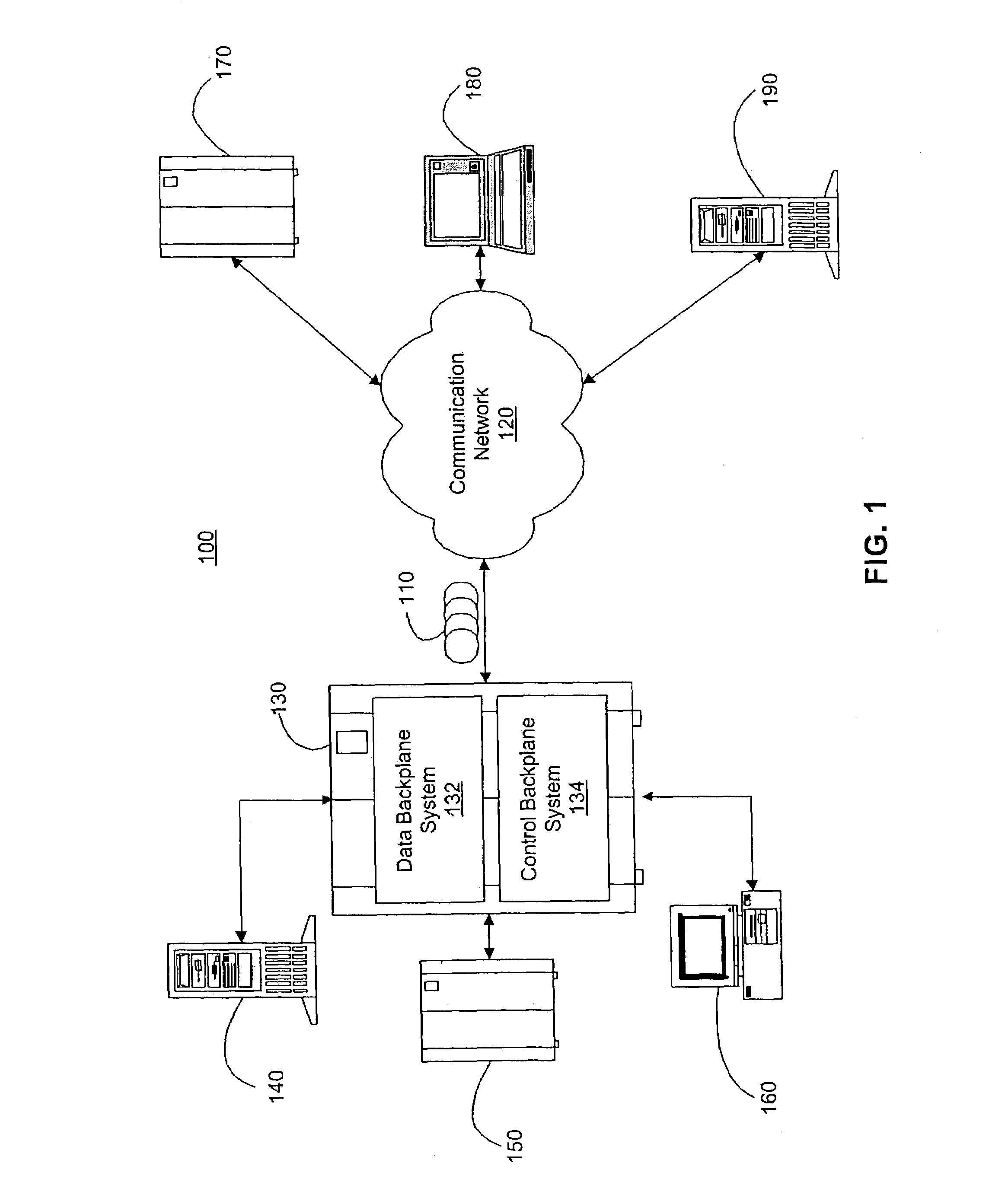
[0020]In the following description various aspects of the present invention, a method and apparatus for using Ethernet as a control communication channel in a packet-forwarding device will be described. Specific details will be set forth in order to provide a thorough understanding of the present invention. However, it will be apparent to those skilled in the art that the present invention may be practiced with only some or all of the described aspects of the present invention, and with or without some or all of the specific details. In some instances, well known architectures, steps, and techniques have not been shown to avoid unnecessarily obscuring the present invention. Reference in the specification to “one aspect of the invention” or “one embodiment” or “an embodiment” means that a particular feature, aspect, structure, or characteristic described in connection with the embodiment is included in at least one embodiment of the invention. The appearances of the phrase “in one em...


PUM


Abstract

A control backplane replaces the traditional shared bus with a dedicated communication channel using a high-speed protocol, such as Ethernet. The resulting system may conduct several concurrent control sessions with clients and devices associated with the network switch. Removing the shared bus from the control plane also improves the reliability of the new system, because it is no longer susceptible to a single point of failure.

Description

[0001]The present patent application is a Continuation of application Ser. No. 10 / 153,842, filed May 21, 2002.TECHNICAL FIELD[0002]The present invention relates to the architecture and operation of network devices. More particularly, the present invention relates to improving delivery of control functions in a packet-forwarding device, such as a switch or router.BACKGROUND AND RELATED ART[0003]In general, packet-forwarding device functions may be characterized into at least two types, data path functions and control functions. Data path functions include operations that are performed on every datagram that passes through the packet-forwarding device, such as a router, where a datagram is an independent, self-contained message sent over the network whose arrival, delivery time, and content are not guaranteed. During the typical path of a packet through an IP router or network switch, the data path functions include the forwarding decision, the backplane, and output communication chan...

Claims


Application Information

Patent Timeline
IPC IPC(8): H04L12/40
CPCH04L49/40H04L49/552H04L49/505
Inventor YIP, MICHAELSCHRODER, STEVE W.GAO, MINXI
Owner EXTREME NETWORKS INC
Learn More