
Signal processing circuit and method using analog voltage signal to pulse width modulation conversion

a signal processing circuit and pulse width modulation technology, applied in the field of signal processing, can solve the problems of insufficient complete satisfaction of speckle-based devices, high complexity and high power consumption, and inability to ensure the measuremen

Inactive Publication Date: 2007-07-24
CYPRESS SEMICON CORP
View PDF5 Cites 80 Cited by
  • Summary
  • Abstract
  • Description
  • Claims
  • Application Information

AI Technical Summary

Benefits of technology

The solution achieves reduced complexity and power consumption, improved accuracy by ensuring measurements are made in the linear region of the TIA, and significantly reduces the impact of reset noise, enhancing the performance of optical navigation systems.

Problems solved by technology

Although a significant improvement over prior art optical mice, these speckle-based devices have not been wholly satisfactory for a number of reasons.
The disadvantages of this approach using one or more ADCs include a relatively high complexity and high power consumption.
In addition, the above approach does not insure that the measurements are made while the TIA is operating continuously in a linear region, and is not saturating before being read by the ADC.
Another problem arises from the fact that the TIA output is reset at the beginning of each sampling period and then allowed to ramp up for a fixed amount of time.
Because the digital value is derived from the output voltage measured at the end of the ramp, this reset noise shows up as noise in the digital value measured, reducing the accuracy of measurement, and therefore the performance of the optical mouse.
However, this increase in accuracy is accomplished at the expense of requiring twice as many analog to digital conversions, and hence doubling the sampling rate required of the ADCs, and requiring additional digital circuitry to store the beginning voltage value and do the subtraction.

Method used


Image

  • Signal processing circuit and method using analog voltage signal to pulse width modulation conversion
  • Signal processing circuit and method using analog voltage signal to pulse width modulation conversion
  • Signal processing circuit and method using analog voltage signal to pulse width modulation conversion

Examples


Embodiment Construction

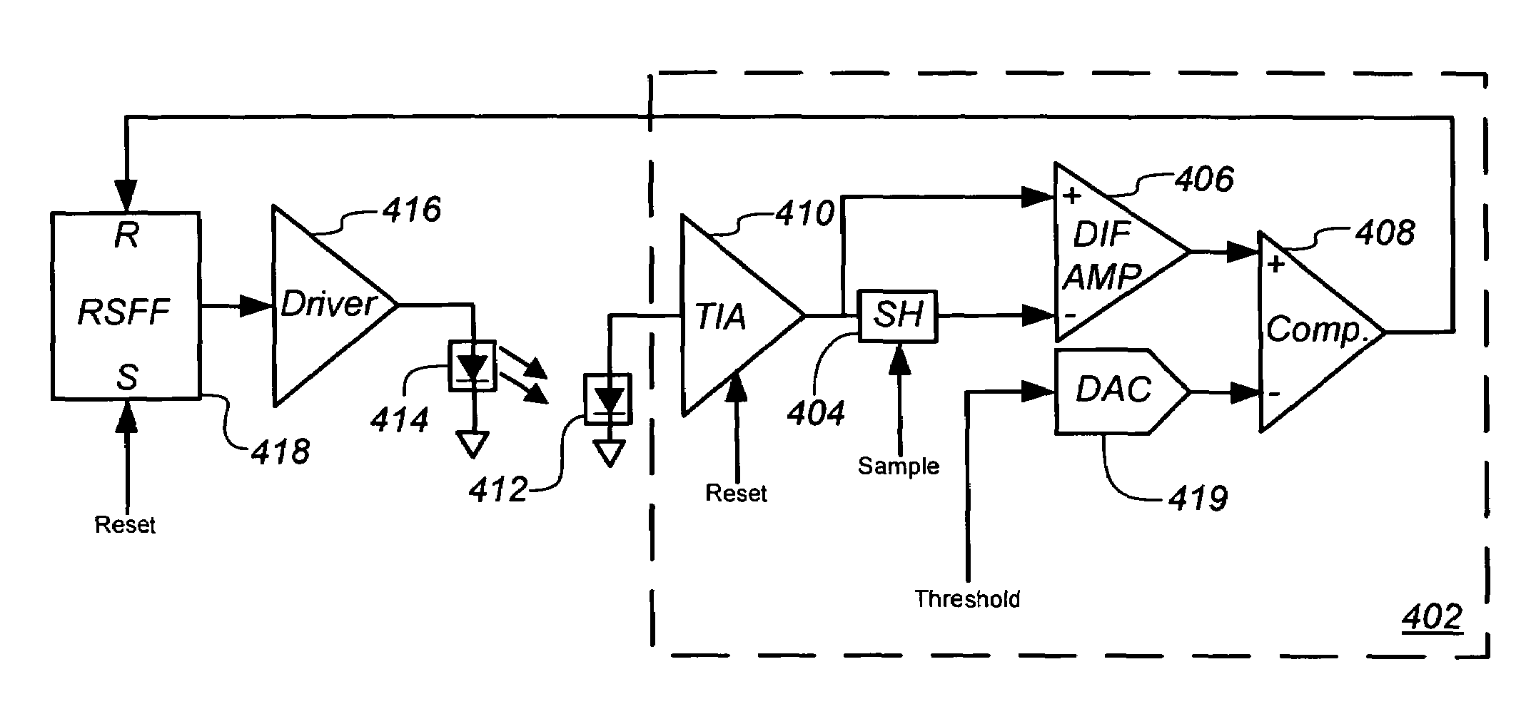
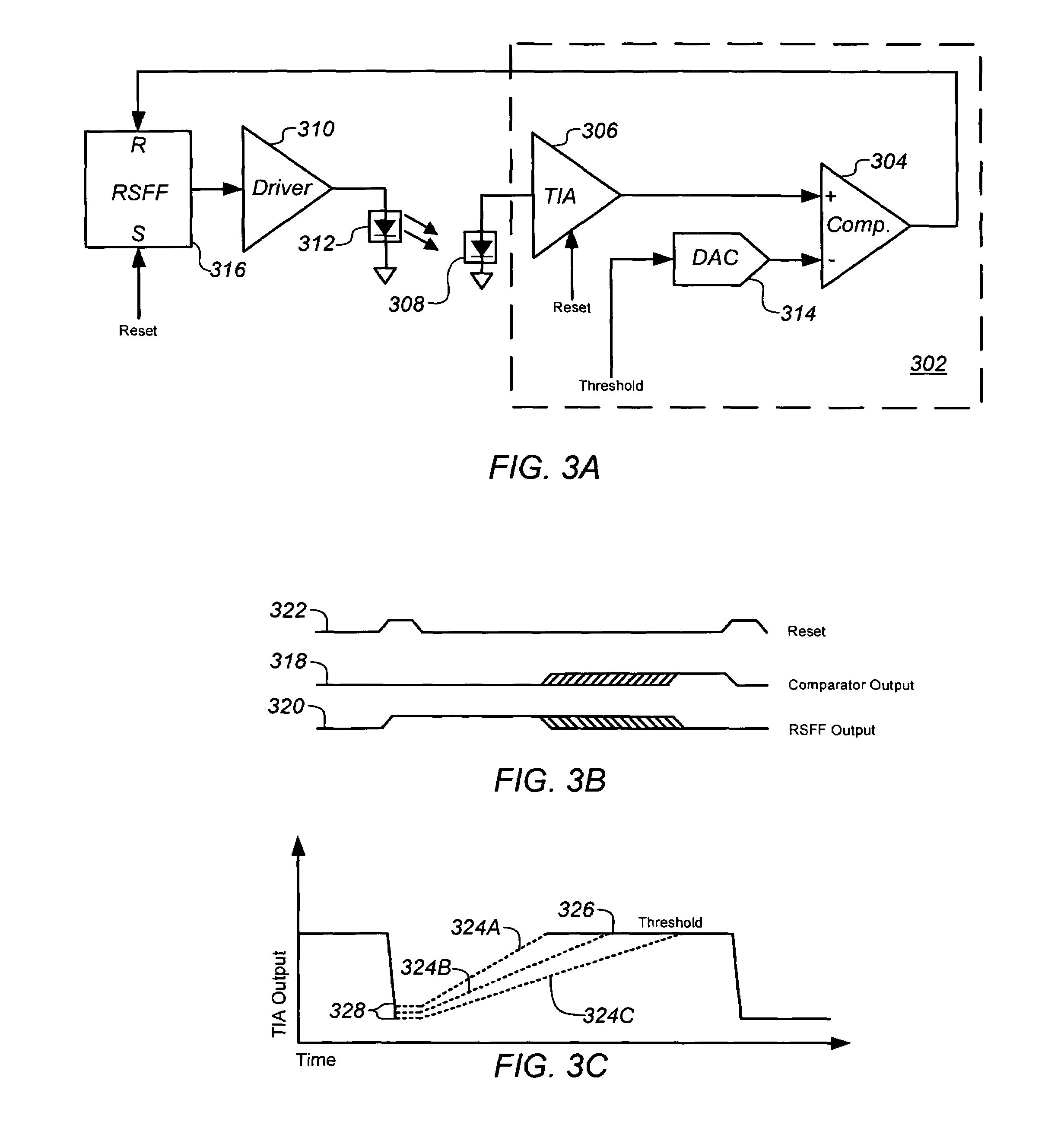
[0033]The present invention is directed to a signal processor or signal processing circuit and method for measuring current received from a photo-detector. The circuit has reduced complexity and power consumption over conventional signal processing circuits, and is substantially independent of and unaffected by reset noise from an integrating transimpedance amplifier (TIA) at the beginning of each sample period.

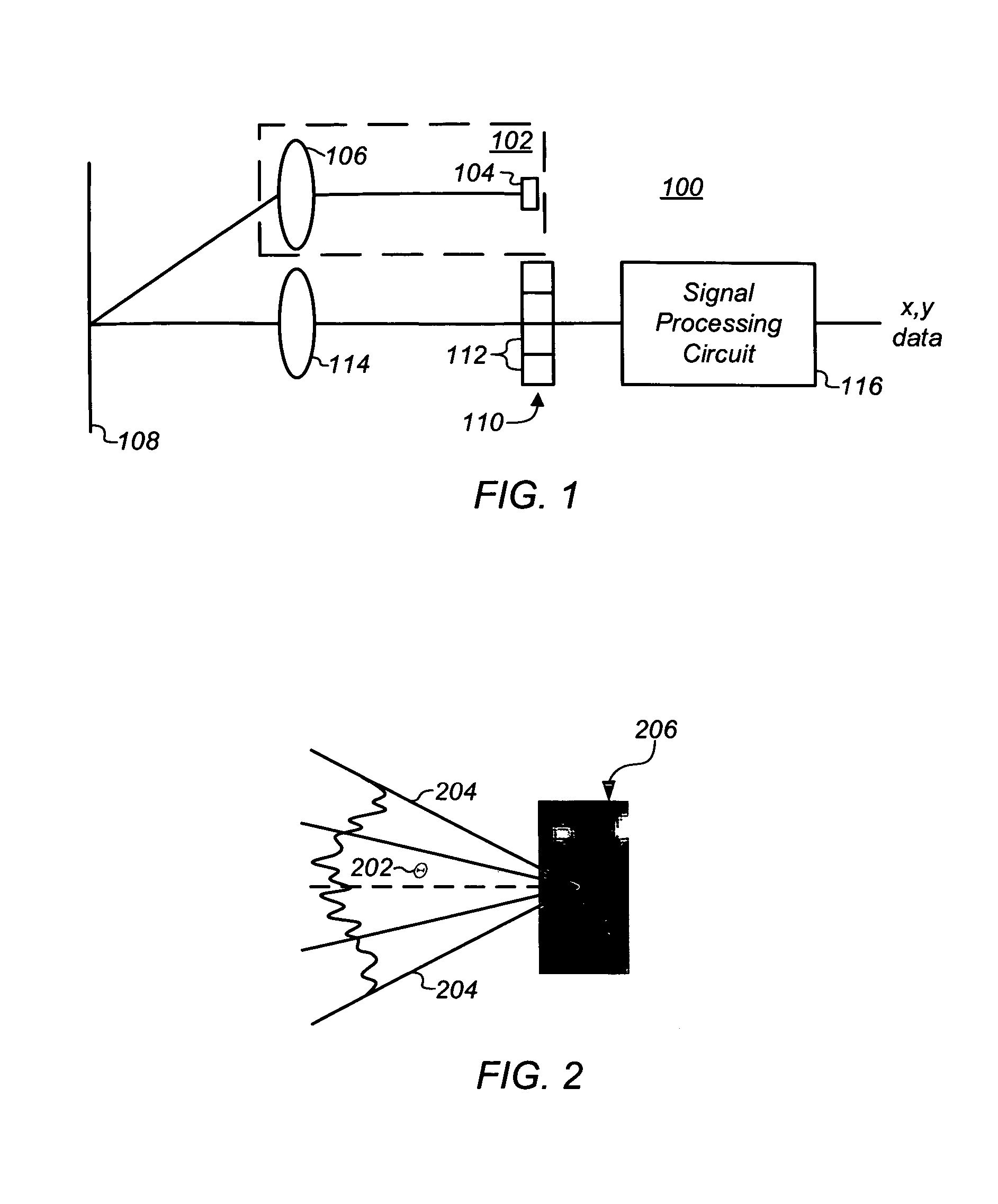
[0034]The signal processing circuit and method are particularly advantageous for processing signals from a photo-detector, such as a photodiode or other light sensitive element, in a photo-detector array used in an optical navigation system, such as an optical computer mouse or an optical trackball.

[0035]For purposes of clarity, many of the details of optical navigation systems in general and signal processing circuits for optical navigation systems in particular that are widely known and are not relevant to the present invention have been omitted from the following descripti...


PUM

PropertyMeasurementUnit
currentsaaaaaaaaaa
currentaaaaaaaaaa
currentaaaaaaaaaa

Abstract

A signal processor and processing method are provided for measuring current received from a photo-detector. Generally, the processor includes a transimpedance amplifier (TIA) to integrate a current received from a photo-detector in the optical navigation system to generate a voltage signal having a slope that is proportional to the received current, and a comparator having a first input coupled to an output of the TIA to receive the voltage signal, and a second, inverting, input coupled to a threshold voltage. The comparator is configured to compare the voltage signal to the threshold voltage and to generate an output pulse having a predetermined voltage and a duration or width that is a function of the received current.

Description

TECHNICAL FIELD[0001]The present invention relates generally to signal processing, and more particularly to a signal processing circuit and method for measuring current received from a photo-detector in an optical navigation device.BACKGROUND OF THE INVENTION[0002]Signal processors are used in a wide range of applications including, for example, measuring a current output from a photo-detector of an array in an optical navigation system. Optical navigation systems, such as an optical computer mouse or trackball, are well known for inputting data into and interfacing with personal computers and workstations. Such devices allow rapid relocation of a cursor on a monitor, and are useful in many text, database and graphical programs. A user controls the cursor, for example, by moving the mouse over a surface to move the cursor in a direction and over distance proportional to the movement of the mouse. Alternatively, movement of the hand over a stationary device may be used for the same p...

Claims


Application Information

Patent Timeline
Patent Type & Authority Patents(United States)
IPC IPC(8): G01J1/44G01N21/86G06M7/00G09G5/08H04N3/14G01J1/32
CPCG01J1/44
Inventor WEBB, DOUGLAS A.
Owner CYPRESS SEMICON CORP
Learn More