Optical rotating data transmission device with coupling slide

a technology of optical rotating data transmission and coupling slide, which is applied in the direction of optical elements, mechanical devices, instruments, etc., can solve the problems of large mechanical speed of movement of the device, so as to achieve reliable transmission, reduce manufacturing costs, and reduce manufacturing costs

Inactive Publication Date: 2007-07-24
SCHLEIFRING & APPBAU
View PDF10 Cites 19 Cited by
  • Summary
  • Abstract
  • Description
  • Claims
  • Application Information

AI Technical Summary

Benefits of technology

[0014]The invention is based on the object of designing a relatively low-cost device for transmitting optical signals between two units that are rotatable relative to each other so that reliable transmission becomes possible with low optical attenuation for large diameters, high mechanical speeds of movement, and high data rates. Furthermore, it is the object of a special embodiment of the invention to design the device so that even signals having period durations that are small by comparison with the time of propagation of light around the circumference of the device may be transmitted.

Problems solved by technology

A basic problem existing here is that of designing a means for carrying light along the circumference of the device, and also suitable means for coupling light in and out.
However, this device is attended by a whole series of disadvantages.
Furthermore, the costs of fabrication are relatively high, owing to the confronting mirror-coated surfaces.
Wideband data transmission with modulation-signal period-lengths which are substantially smaller than the transit time of the light around the circumference of the device is not possible, because a multiple-path reception of signals occurs at receiver positions close to a transmitter.
However, also this patent specification describes no effective solution of the problem of bandwidth limitation.
In addition, the proposed coupling-in or coupling-out of light by blunt fiber ends can be achieved only with an extremely poor efficiency.
However, here too a large attenuation of the optical transmission path results, because the coupling-in mirrors cannot be placed arbitrarily close to the mirror-finished cylinder, in particular at high speeds of movement.
Moreover, an unavoidable fanning of the light beam on the plane mirror surface results in an additional deterioration of efficiency.
Furthermore, the mechanical construction of the coupling-out element involves much outlay, and is therefore liable to failure, and costly.
Finally, the problem of bandwidth limitation is not solved.
Here too, the limitation applies that the period length of the modulation signal must be substantially smaller than the transit time of the light around the circumference of the device.
However, this system involves much outlay, is expensive to fabricate, and is suitable only for small diameters.
Furthermore, here too the wideband problem has not been solved.
Thus, the system costs rise in proportion to the band width.
This arrangement has the decisive disadvantage that the coupling medium must directly contact the fiber core.
A system of this kind is, however, hardly applicable to arrangements in which a transmitter and a receiver move relative to each other, because here the coupling medium must move at a high speed along a usually very thin and sensitive fiber core.
However, with conventional highly precise bearing means, this accuracy can be achieved only with small dimensions of the entire arrangement.
Therefore at present this system cannot be used, for example in computer tomographs having a diameter of 1.5 meters and circumferential speeds of up to 20 m / s.

Method used


Image

  • Optical rotating data transmission device with coupling slide
  • Optical rotating data transmission device with coupling slide
  • Optical rotating data transmission device with coupling slide

Examples


Embodiment Construction

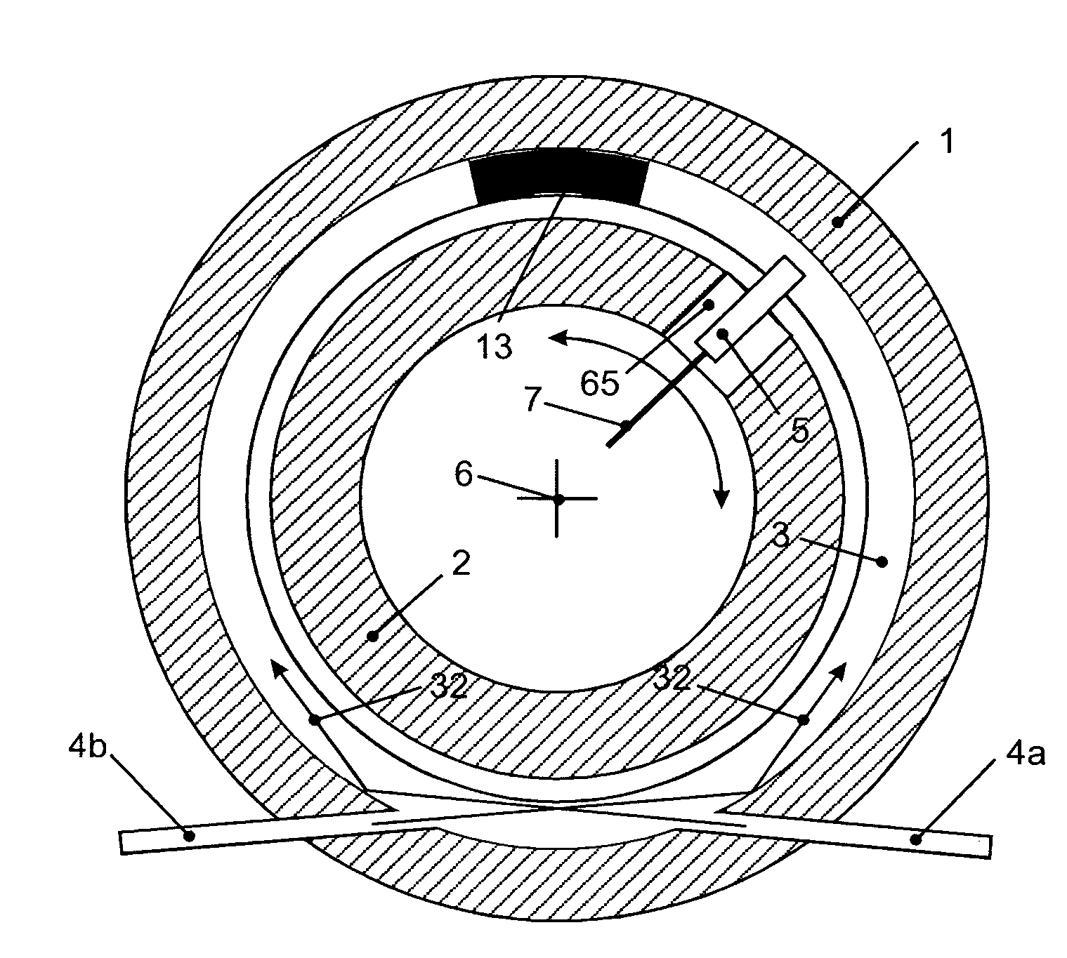
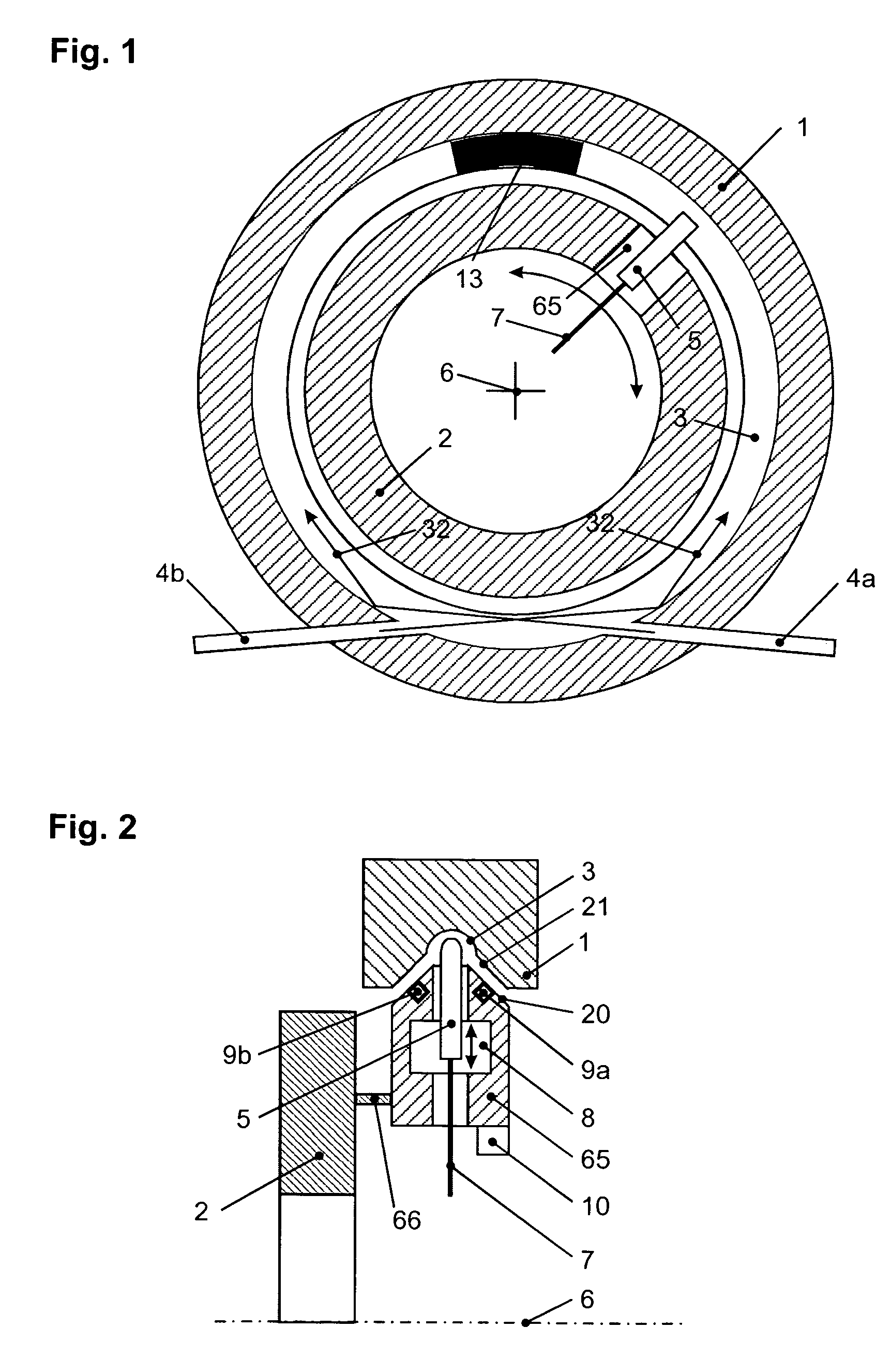
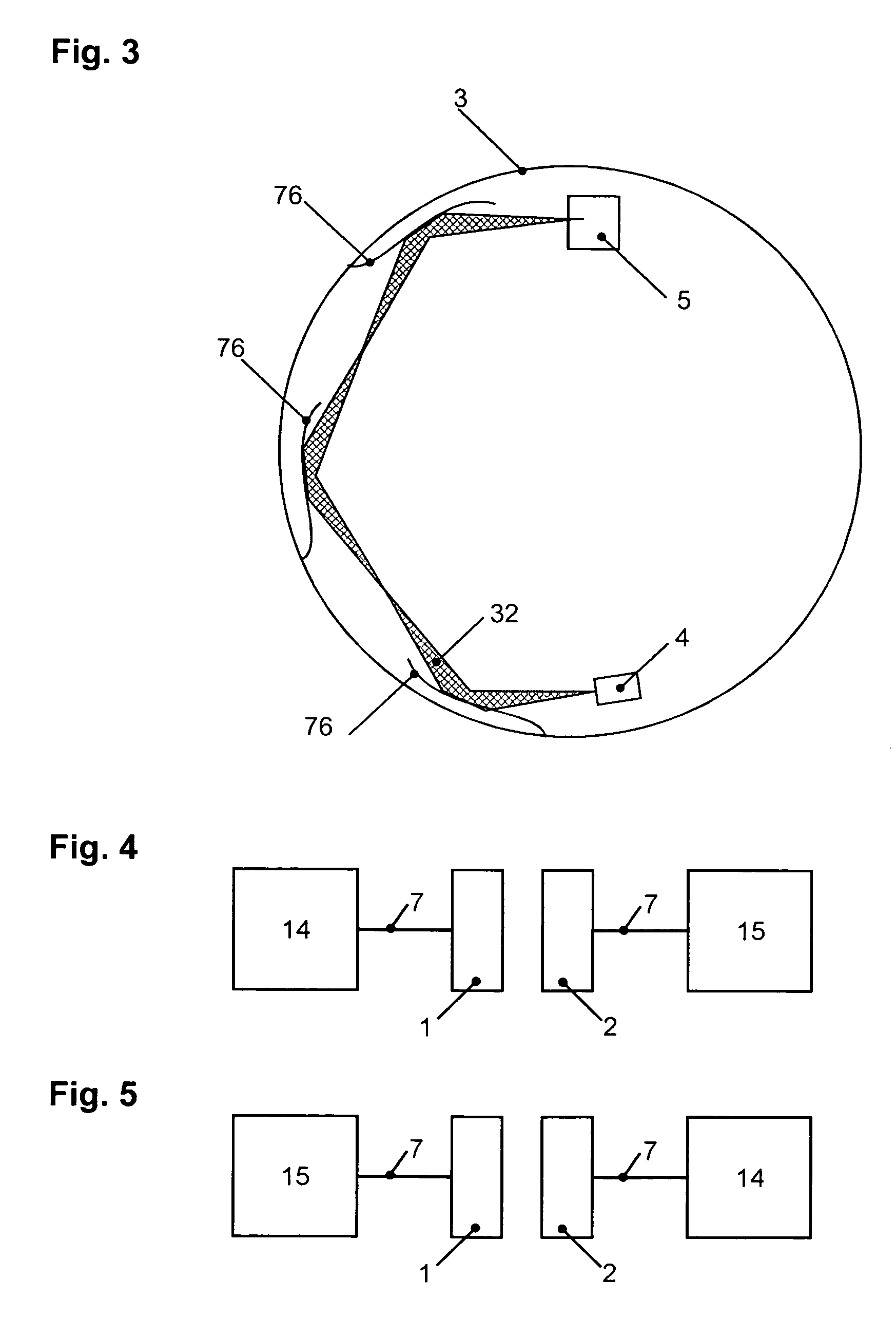
[0042]The device in accordance with the invention comprises a light guide that is disposed along a given track, preferably a circular track, on a first unit. For the sake of simplicity, only one light guide will be described here. Of course, a plurality of arrangements in accordance with the invention, each having one light guide, may be connected in parallel. Connected to the light guide is at least one first light coupler for coupling light into or out of the light guide. At least one optical transmitter or receiver is connected to at least one of these first light couplers. Whether a transmitter or receiver is to be connected to the light guide is determined by the desired direction of transmission. If light is to be transmitted away from the light guide, then a transmitter must be provided, and a receiver in the other case. Of course, for transmitting information, the optical transmitters are adapted to be modulated with a modulation signal.

[0043]Furthermore, a second unit is pr...


PUM


Abstract

A device for transmitting modulated optical signals between a first unit and a second unit, in which the first unit is supported to be rotatable or movable linearly relative to the second unit, comprises a light guide extending along a given track on the first unit, a first light coupler for coupling light into and out of the light guide, and a second light coupler disposed on the second unit and movable relative to the light guide for coupling light into and out of the light guide. A coupling slide is provided for supporting the second light coupler, and is mechanically loosely connected to the second unit via a take-up unit so that the coupling slide is moved along the given track together with the second unit by a movement of the second unit.

Description

CROSS REFERENCE TO RELATED APPLICATIONS[0001]This application is a continuation of pending International Application No. PCT / EP2004 / 008834 filed Aug. 6, 2004, which designates the United States and claims priority from pending German Application No. 103 36 925.2 filed Aug. 7, 2003BACKGROUND OF THE INVENTION[0002]1. Field of the Invention[0003]The invention relates to a device for transmitting optical signals between units that are rotatable relative to each other. Devices of this kind are used preferably in computer tomographs.[0004]2. Description of the Prior Art[0005]Various devices are known for transmitting optical signals between units that are rotatable relative to each other, particularly those having an unobstructed inner diameter. A basic problem existing here is that of designing a means for carrying light along the circumference of the device, and also suitable means for coupling light in and out. For use in computer tomographs, devices of this kind must have large unobst...

Claims


Application Information

Patent Timeline
Patent Type & Authority Patents(United States)
IPC IPC(8): G02B6/26F21V8/00G02B6/10G02B6/34G02B6/36H04B10/00
CPCG02B6/0096G02B6/10G02B6/26G02B6/34G02B6/3604H04B10/225H04B10/25
Inventor SCHILLING, HARRYSCHOPPEL, GUENTHERRANK, MATTHIAS
Owner SCHLEIFRING & APPBAU
Why Eureka
Try Eureka