Beam tracking system for scanning-probe type atomic force microscope

a beam tracking and scanning-probe technology, applied in the direction of mechanical measurement arrangement, mechanical roughness/irregularity measurement, instruments, etc., can solve the problems of affecting the performance of piezoelectric scanners, difficult to obtain correct images by using scanning-sample type afm, and problems such as the inability to move or position samples, so as to reduce horizontal and vertical tracking errors

Inactive Publication Date: 2007-07-31
ACAD SINIC
View PDF8 Cites 27 Cited by
  • Summary
  • Abstract
  • Description
  • Claims
  • Application Information

AI Technical Summary

Benefits of technology

[0009]Another objective of this invention is to provide a light path system for scanning-probe type atomic force microscope wherein both horizontal and vertical tracking errors may be reduced.SUMMARY OF THE INVENTION

Problems solved by technology

Problems in moving or positioning the sample arise when the sample is large or heavy.
In addition, temperature control, such as heating or cooling, of the sample may also affect the performance of the piezoelectric scanner of the AFM, which is provided beneath the sample.
For samples in liquid cell, such as biomolecules, it is difficult to obtain correct images by using a scanning-sample type AFM, since samples move during the scan.
However, the optical detecting module, including the laser diode (LD), the photo sensing device (PSD), the alignment mechanism and the frame structure that supports the optical configuration, is often too bulky and too massive to move with the scanner.
Moving the whole module to scan the sample is proved not ideal.
Under such a design, however, the tracking error will limit the resolution of the microscope.
If the PSD signal varies during the scanning while deflection of the probe is null, false deflection or optical tracking error is generated.
In these systems, however, the tracking function applies to false deflections in the horizontal directions but not in the vertical direction.
However, the intensity signal of the beam varies if some portions of the beam fall-off the probe due to defocusing of the laser spot on the probe, whereby the shape of the reflected beam will be warped on the PSD and the PSD position signal will he adversely affected.
Under such a design, its installation will readily limit one dimension of the image size.
Another disadvantage of the twist-probe rests in that its distance to the PSD varies during the scanning, whereby constant relation between the probe deformation and the PSD signal can not be guaranteed.

Method used


Image

  • Beam tracking system for scanning-probe type atomic force microscope
  • Beam tracking system for scanning-probe type atomic force microscope
  • Beam tracking system for scanning-probe type atomic force microscope

Examples


Embodiment Construction

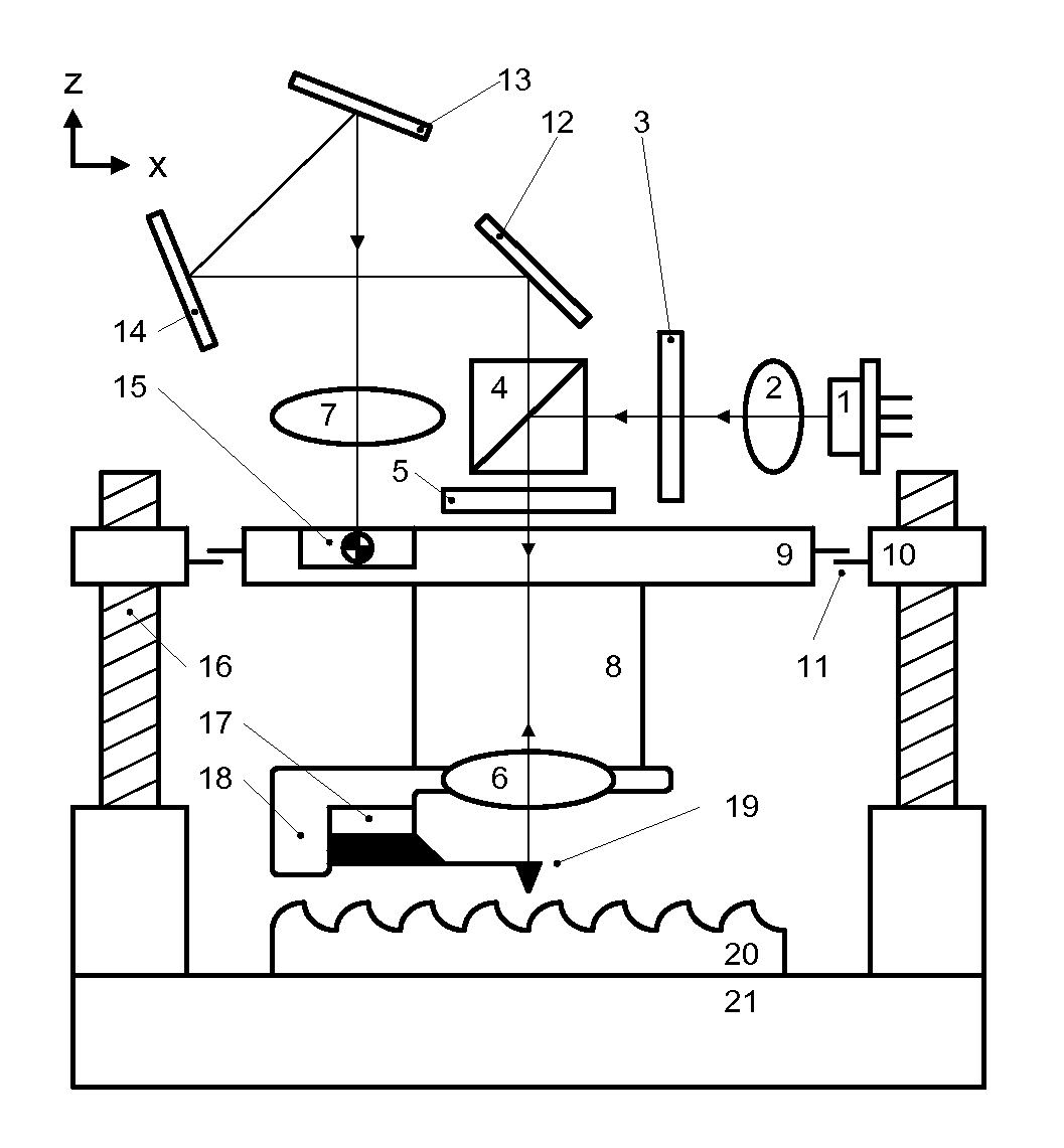
[0029]FIG. 1 shows the systematic diagram of the beam tracking system for the scanning-probe type atomic force microscope of this invention. As shown in this figure, the beam tracking system for the scanning-probe type atomic force microscope of this invention comprises a base unit, a laser source unit, an optical unit and a feedback unit. In these units, laser source 1 is used to generate a laser beam. The laser beam generated by laser source 1 is collimated by a collimation lens 2, polarized by a polarizer 3 and enters a beam splitter 4. The laser beam is then partially reflected and reaches the objective lens 6 through the ¼λ wave plate 5. The probe 19 is positioned at approximately the focal point of the objective lens 6, where the objective lens 6 focuses the laser beam at the probe 19. The laser beam reflected from the probe 19 contains deflection information of the probe 19. It reaches mirrors 12, 13 and 14 via objective lens 6, ¼ wave plate 5 and beam splitter 4, and is intr...


PUM

PropertyMeasurementUnit
scanning distanceaaaaaaaaaa

Abstract

Disclosed is a novel scanning-probe type atomic force microscope wherein false deflection of the probe is reduced. The probe of the scanning-probe type atomic force microscope moves in both the horizontal direction and the vertical direction during the scanning, while the sample is kept in order to reduce the false deflection brought to the probe due to the scanning motion, two approaches are adopted. The first is to have a focused laser spot tracking an invariant point on the probe's cantilever, which moves three-dimensionally during the scanning. The second approach is to have the laser beam, which is reflected from the moving cantilever, hitting an invariant point of the PSD, when the sample is distanced from the probe and induces no deflection. A beam tracking system wherein the scanning probe is located approximately at the focal point of an objective lens and he optical system including a laser source, an optical module, a feedback module and the probe are driven by an approach mechanism to move in synchronization.

Description

FIELD OF THE INVENTION[0001]The present invention relates to an optical path design of scanning-probe type atomic force microscope, especially to a beam tracking system for scanning-probe type atomic force microscope. The present invention is especially useful in reducing the false deflection of the probe of the scanning-probe type atomic force microscope when the probe is moving at high speed in the three-dimensional space, whereby correct measurement results may be obtained.BACKGROUND OF THE INVENTION[0002]The atomic force microscope (AFM) may be used to produce three-dimensional images of a surface with the resolution of the nanometer level. There are two types of AFM. One is the “scanning-sample type” atomic force microscope and the other is the “scanning-probe type” atomic force microscope. In a scanning-sample type AFM, the sample is moved when it is scanned and the probe is kept stationary. Problems in moving or positioning the sample arise when the sample is large or heavy. ...

Claims


Application Information

Patent Timeline
Patent Type & Authority Patents(United States)
IPC IPC(8): G01B5/28G01N13/16G01Q10/00G01Q20/02G01Q60/24G01Q70/02
CPCB82Y35/00G01Q70/02G01Q20/02
Inventor HWANG, ING-SHOUHHUNG, SHAO-KANGFU, LI-CHENLIN, MING-YEN
Owner ACAD SINIC
Why Eureka
Try Eureka