
Microwave hyperthermia treatment apparatus and treatment system

a treatment device and hyperthermia technology, applied in the field of microwave hyperthermia treatment devices and treatment systems, can solve the problems that the technology cannot achieve the necrosis of cancerous tumors, and achieve the effects of reducing the period of hyperthermia treatment, suppressing the temperature rise on the skin, and sufficient temperature ris

Inactive Publication Date: 2007-07-31
INTELEX
View PDF3 Cites 0 Cited by
  • Summary
  • Abstract
  • Description
  • Claims
  • Application Information

AI Technical Summary

Benefits of technology

"The present invention is a microwave hyperthermia treatment device that can provide a more efficient and comfortable treatment for patients. The device includes a generation unit for generating microwaves, a power supply unit for driving the generation unit, and a control unit for controlling the power supply unit. The control unit includes an exposure-time actuation timer, an intermittent actuation timer, a second-device connecting terminal, and a remote switch connected with a remote-control cord. The device can be used by connecting two microwave treatment devices together, allowing for a faster treatment of affected areas. The device also includes a second-device connecting terminal and remote switches for patient self-operation. The device can adjust output from a high output to a low output by adjusting the intermittent actuation timer, and it can be used for treating arthritis, chronic rheumatism, or the like by connecting two microwave treatment devices. The device can also reduce the burden on patients by reducing the treatment period and allowing for faster recovery."

Problems solved by technology

Since the output energy reaching an affected part is attenuated within a subject's body, with thus attenuated output energy levels, although it may be termed thermotherapy, the technology is unable to achieve necrosis of cancerous tumors.
Nevertheless, the conventional techniques discussed above each employ a single microwave treatment device and irradiate microwaves continuously for approximately one hour.

Method used


Image

  • Microwave hyperthermia treatment apparatus and treatment system
  • Microwave hyperthermia treatment apparatus and treatment system
  • Microwave hyperthermia treatment apparatus and treatment system

Examples


embodiment 1

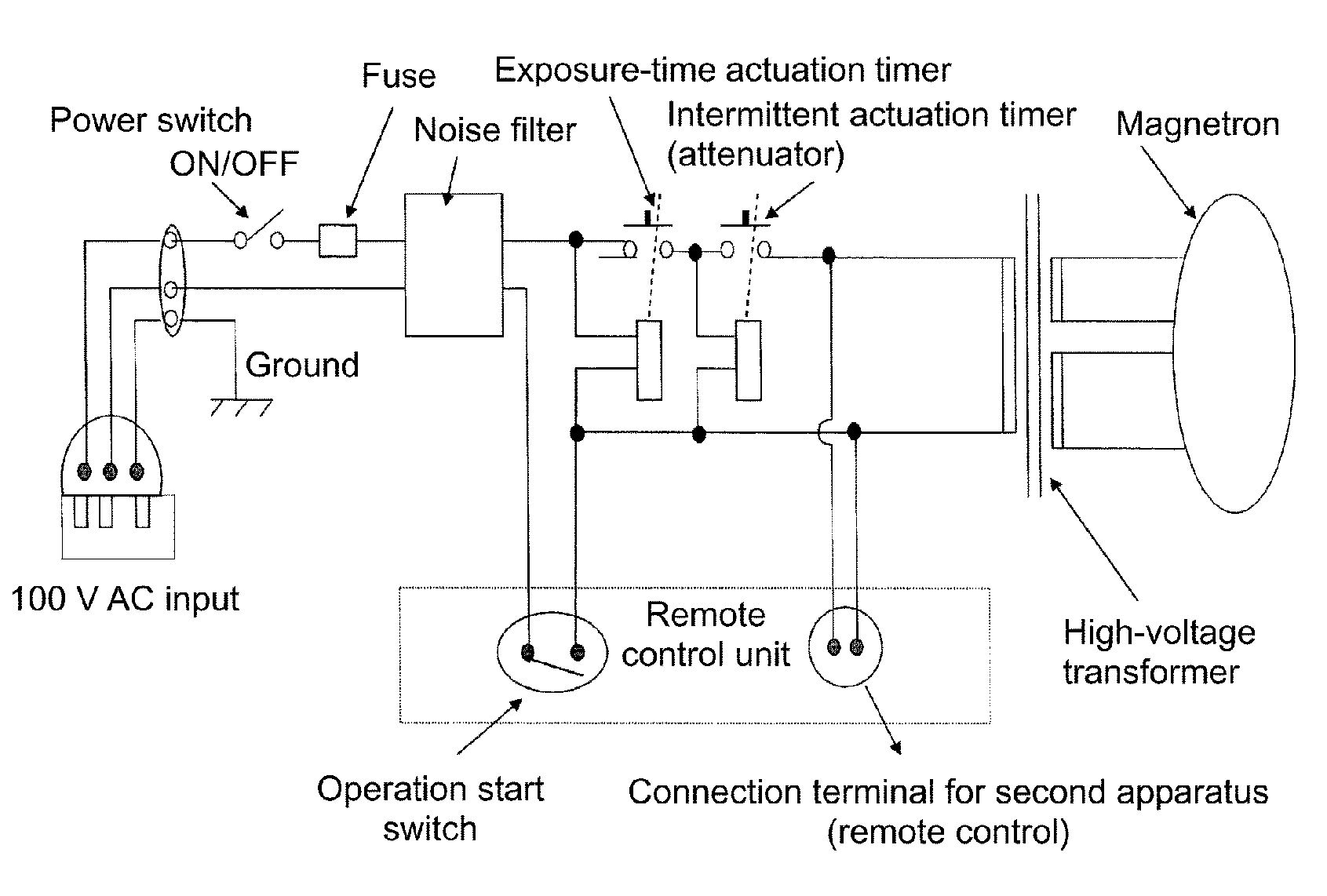
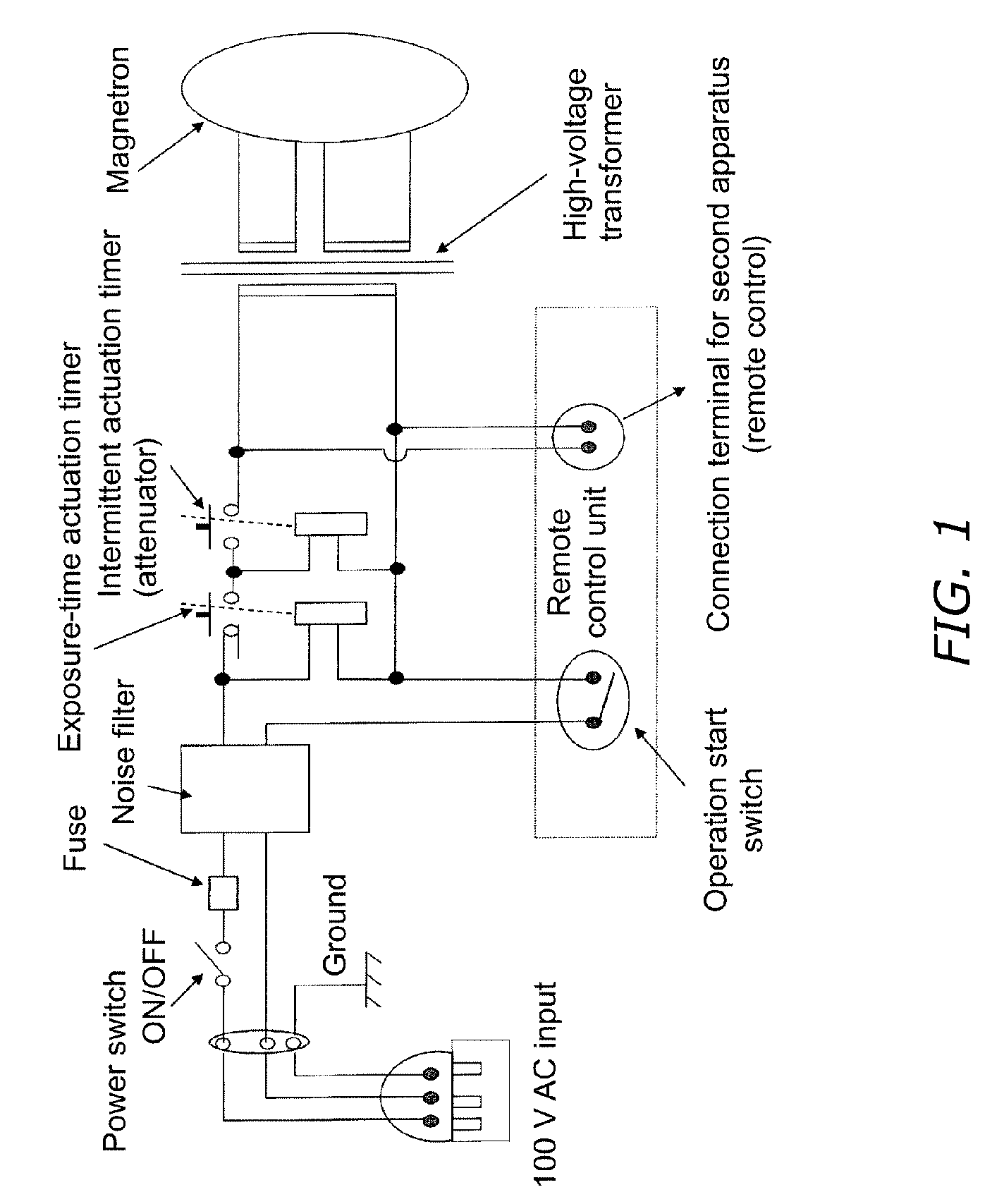
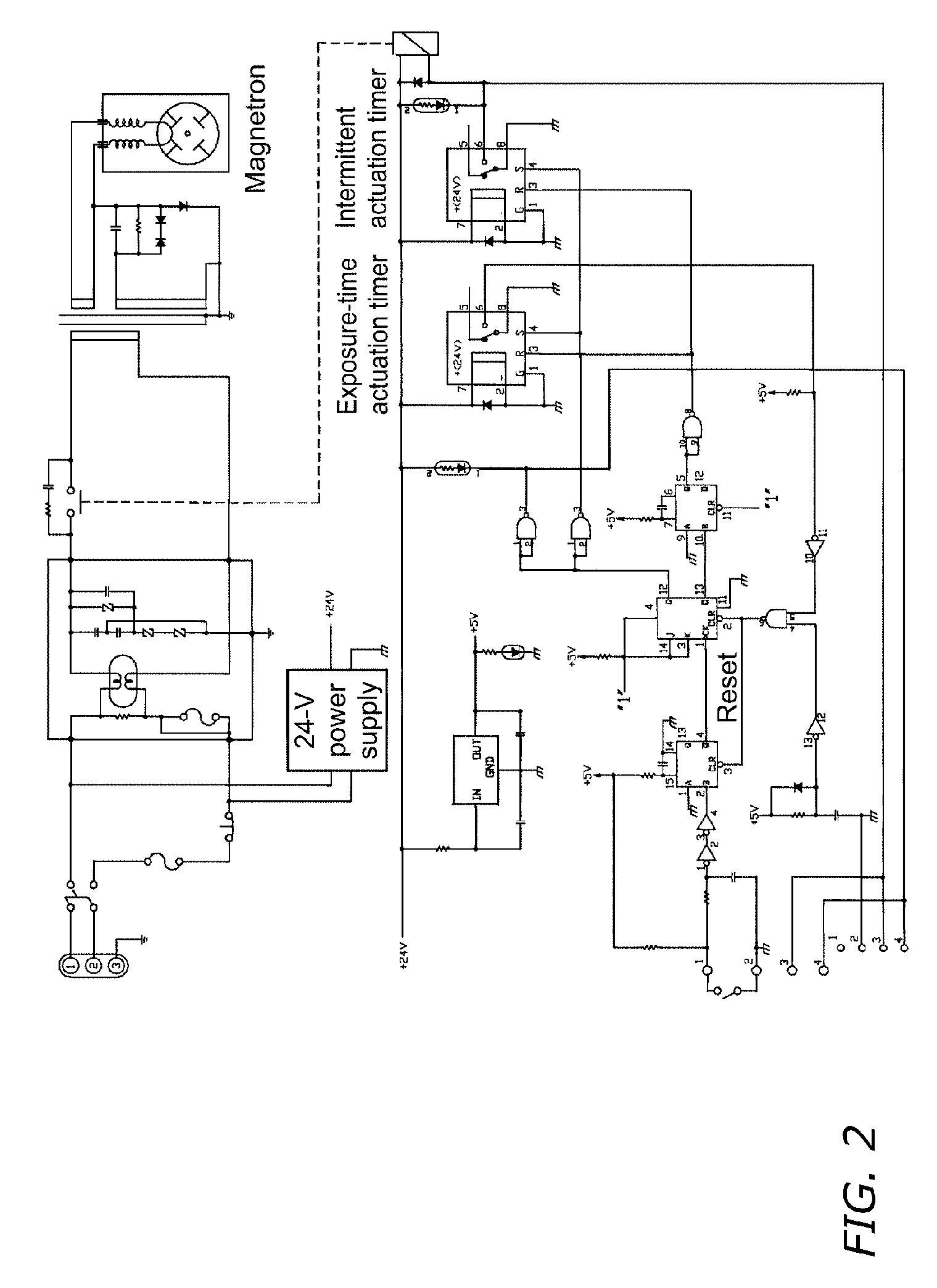
[0046]FIG. 1 is a block diagram showing an embodiment 1 of a microwave hyperthermia treatment device of the present invention. FIG. 2 is a circuit diagram of the microwave hyperthermia treatment device of the present invention.

[0047]The high-pressure transformer employed in Embodiment 1 is a well-known one, in which the primary side input is 100 V and the secondary side output is 4,000 V. Further, the magnetron employed is a well-known one, in which the frequency is 2,450 MHz and the rated output is 750 W.

[0048]The microwave hyperthermia treatment device unit 1 of the present invention is mounted on a swing mechanism 4 disposed on the upper part of a vertical mechanism 3 provided on a caster 2 with five legs.

[0049]The configuration described above is shown in FIG. 3, as a front view of the microwave hyperthermia treatment device.

[0050]The swing mechanism 4 has a swing clamp 5, capable of moving the microwave hyperthermia treatment device unit 1 in vertical and horizontal directions....

embodiment 2

[0075]Embodiment 2 is an example in which a connecting cable (not shown) is connected to the second-device connecting terminal 11 of the microwave hyperthermia treatment device of Embodiment 1 and the other end of the connecting cable is connected to a second-device connecting terminal 11 of a second microwave hyperthermia treatment device. The two devices are used at the same time so as to flank, along both sides of an affected area, a patient's torso.

[0076]The configuration described above is shown in FIG. 7A, as a schematic diagram showing in which the two microwave hyperthermia treatment devices of the present invention are used at the same time.

[0077]The microwave irradiation angle in the case of using two microwave hyperthermia treatment devices of the present invention can be set to any angle within a range from about 90° to 180°. In FIG. 7A, they are used at 180° with the torso between them.

[0078]The operating method of using two microwave hyperthermia treatment devices conn...

embodiment 3

[0094]FIG. 7B shows an example in which a connecting cable (not shown) is connected to the second-device connecting terminal 11 of the microwave hyperthermia treatment device of Embodiment 1, and the other end of the connecting cable is connected with a second-device connecting terminal 11 of the second microwave hyperthermia treatment device, and a third microwave hyperthermia treatment device unit 1′ and a forth microwave hyperthermia treatment device unit 1′ are connected in series in the same manner to thereby use the four devices at the same time while flanking affected areas along both sides.

[0095]Given a setting example of the exposure-time actuation timer 7 and the intermittent actuation timer 9 and an operating method in the embodiment 3 for reference, the set value of the exposure-time actuation timer 7 is 30 minutes, the set value of the ON time of the intermittent actuation timer 9 is 1 second, and the set value of the OFF time is 15 seconds. In this setting example, the...


PUM


Abstract

Microwave hyperthermia treatment device includes a microwave generation unit, a power supply unit, and a control unit including an exposure-time actuation timer, an intermittent actuation timer, a second-device connecting terminal, and a remote switch. Two microwave hyperthermia treatment devices are connected with each other via the second terminal connecting terminals for simultaneous use flanking the torso along either side of an affected area, whereby superposed strong microwaves are irradiated. The temperature of tumor(s) in the affected area can thereby be brought to about 43° C. in about 1 minute, rendering lengthy treatment periods unnecessary and thus alleviating temperature stress on the patient. Two remote-control switches to the control unit can be provided, one of which may be given to a patient for use as an emergency stop switch, eliminating the necessity of having to insert a temperature sensor in the body, which also alleviates the burden on the patient.

Description

BACKGROUND OF THE INVENTION[0001]1. Technical Field[0002]The present invention relates to microwave-employing hyperthermia treatment devices and treatment systems.[0003]2. Description of the Related Art[0004]That a one-degree rise in human body temperature increases immunological competence by 30% is conventional knowledge, and a variety of thermotherapeutic techniques taking advantage of that fact are available. With microwave treatment devices, an extremely weak output is used for treating arthritis, chronic rheumatism, and similar diseases.[0005]Achieving necrosis of cancerous tumors by putting the human body into hyperthermia of about 43° C. is also conventional knowledge. There are a variety of means by which the body can be put into hyperthermia, among which raising temperature by exposing the body to microwave energy is known.[0006]A specific such example is in Japanese Unexamined Pat. App. Pub. No. S61-33668, in which an affected part of a patient's body is exposed to microw...

Claims


Application Information

Patent Timeline
Patent Type & Authority Patents(United States)
IPC IPC(8): H05B6/64A61F7/00
CPCA61N5/02
Inventor YAMAMOTO, RYUICHI
Owner INTELEX
Learn More