Lateral force resisting system

a technology of lateral force and resistance system, which is applied in the direction of gaseous heating fuel, domestic stoves or ranges, lighting and heating apparatus, etc., can solve the problems of many failures, many failures of plywood sheathed shearwalls, and limited structural contribution of drywall panels, so as to improve the lateral force resistance of building frames

Inactive Publication Date: 2007-08-07
TIMMERMAN SR TIMOTHY L +1
View PDF30 Cites 43 Cited by
  • Summary
  • Abstract
  • Description
  • Claims
  • Application Information

AI Technical Summary

Benefits of technology

[0017]In accordance with the present invention, lateral force resistance of a building frame may be improved by substituting a manufactured steel lateral force resisting system, which includes a tailored ductility structural panel and may include holdowns, in place of each conventional sheathed shearwall. In addition, a foundation bolt placement template may also be used. The lateral force resisting system may be used in wood frame as well as metal frame buildings.

Problems solved by technology

The structural contribution of a drywall panel is limited because of the relatively delicate composition of the drywall.
Review of damage following the Northridge earthquake, revealed that many plywood sheathed shearwalls failed under the seismic forces.
The nailing of the sheathing in the field during construction leads to many failures.
Nail heads penetrate the skin of the sheathing during nailing which weakens the sheathing and allows the nails to be pulled through the sheathing under load conditions as well as inducing failures in the integrity of the sheathing.
Current field fabrication techniques are not sufficiently accurate to consistently meet the design specifications.
The interface between the shearwall and the foundation may also be area of weakness.
Quite often the bolts which are supposed to secure the walls and shear panels are placed several inches away from where they are required for optimum load transfer and ease of wall construction due to inaccurate measuring and carelessness during field installation of the bolts.
The resulting attachment of the wall to the foundation is a potential point of failure.
Another common fabrication error is oversize holes in the mudsill.
Many different causes result in holes in the mud sill which don't line up with the bolts placed in the foundation or in the stem wall.
This requires extra holes, or oversize or elongated holes be created in the mud sill which may weaken the frame-foundation interface.
The attachment hardware that may be used to connect a shearwall to the foundation may be another point of weakness.
If a field-fabricated shearwall were ever built in exact compliance with the design, the attachment hardware would likely fail before the shearwall.
In other cases, the method of attaching the attachment hardware to the studs induces cracking of the studs.

Method used


Image

  • Lateral force resisting system
  • Lateral force resisting system
  • Lateral force resisting system

Examples


Embodiment Construction

)

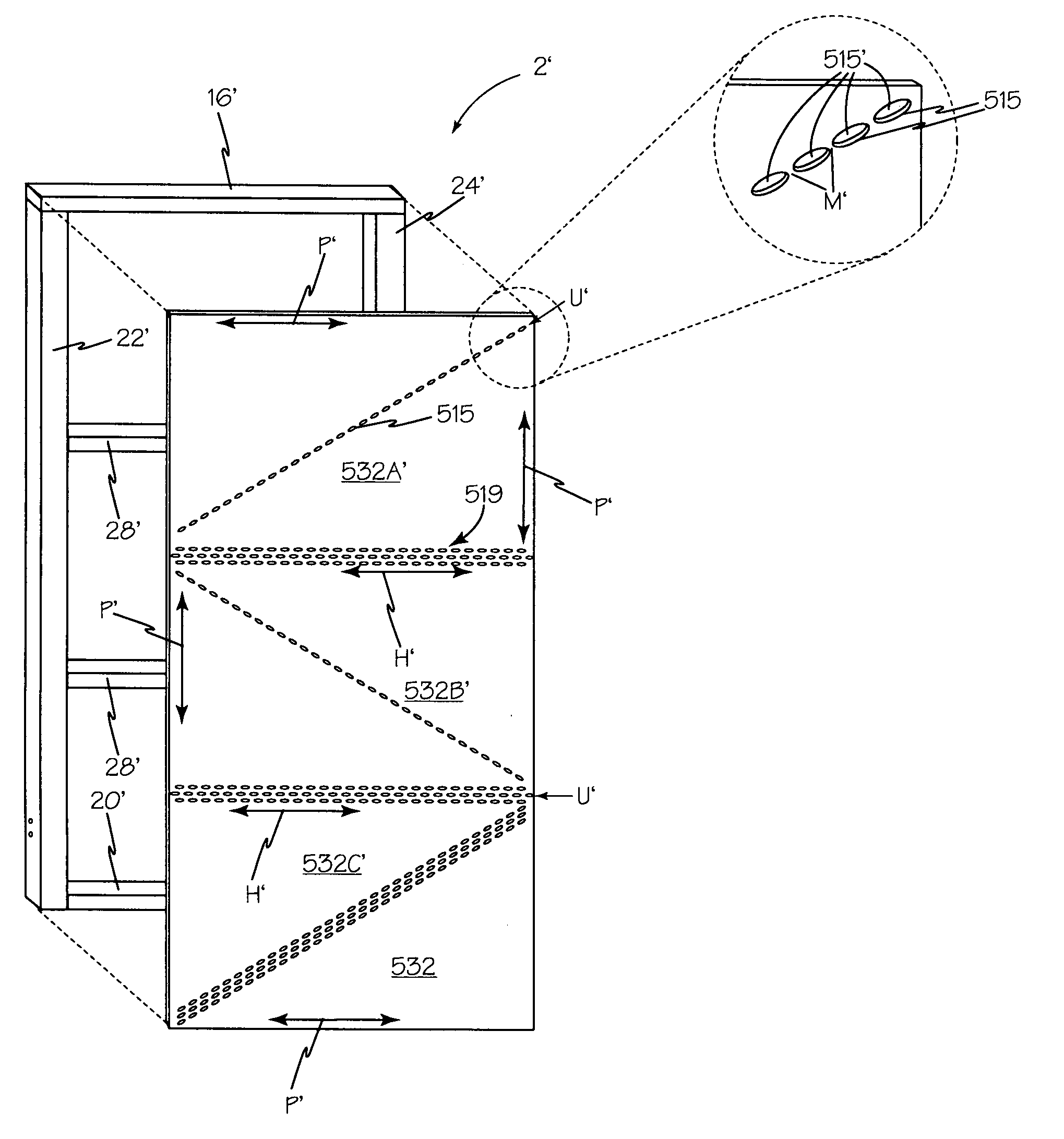
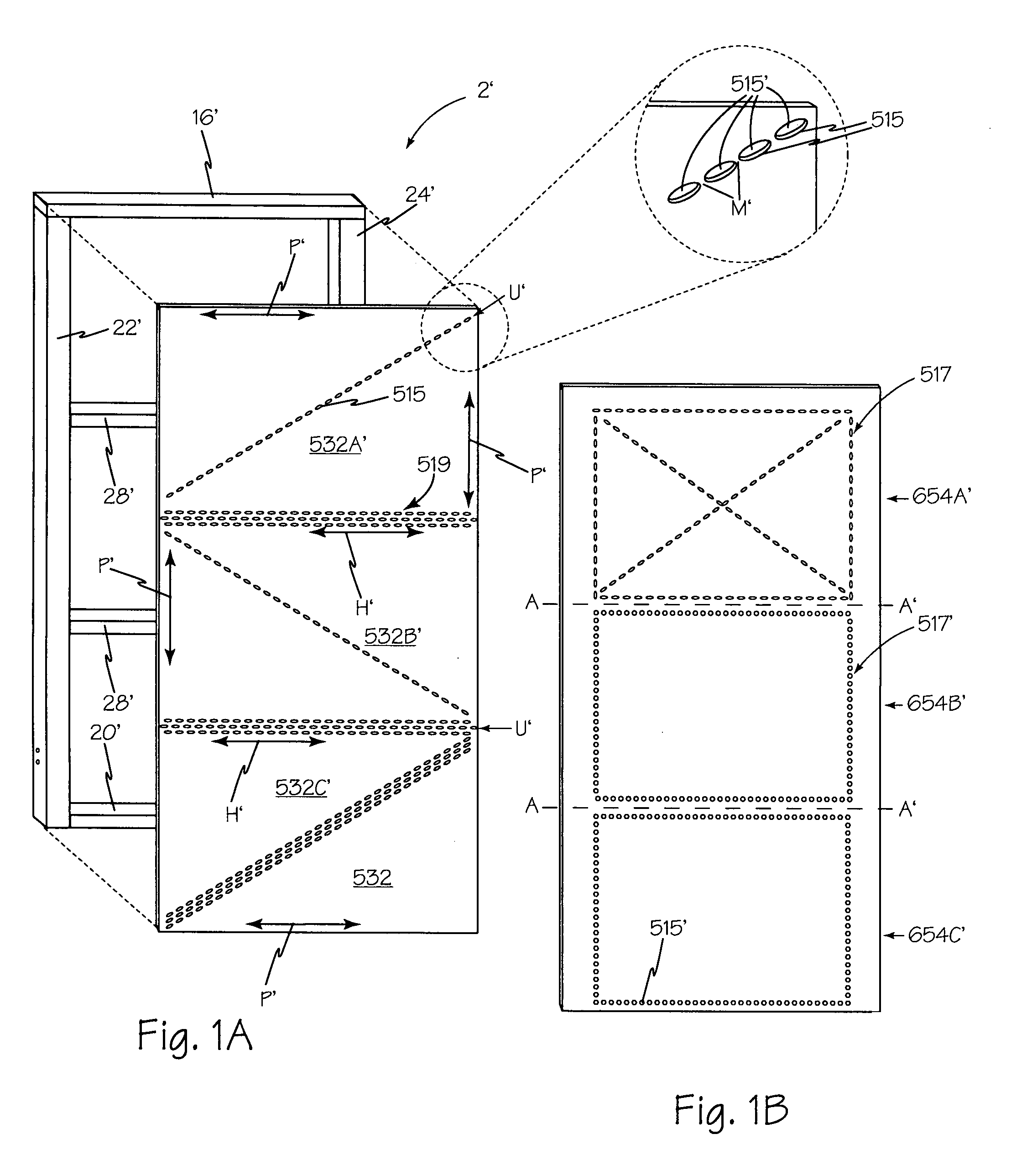
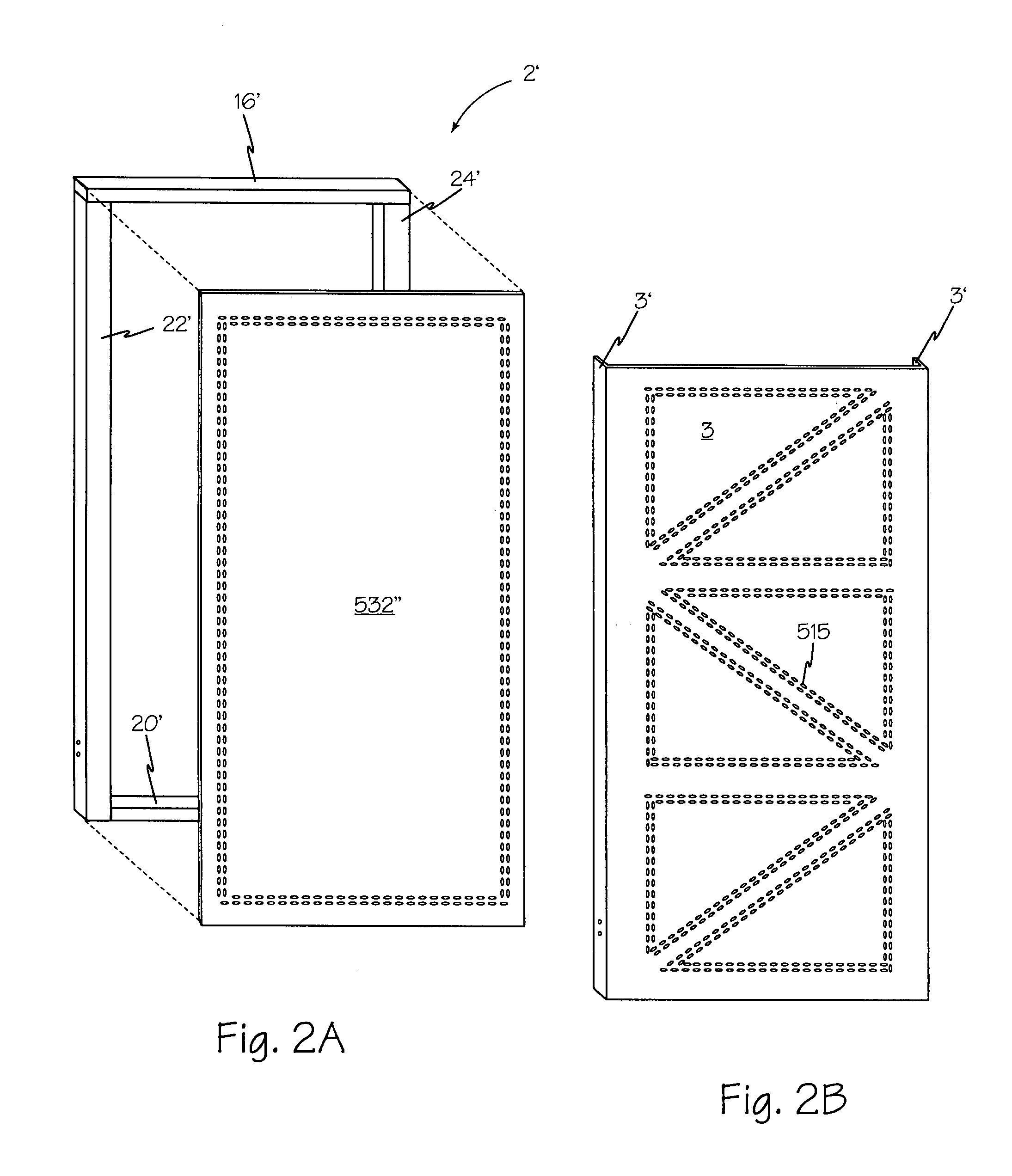
[0047]Referring now to FIG. 3, a front view of a currently preferred embodiment of the present invention, showing rigid structural panel 2, secured to foundation 4, by foundation bolt placement template 14 and holdowns 6 and 8 engaged to foundation bolts 10 and 12 respectively. Furring boards 26 and 26A are attached to first side member 22 and second side member 24 respectively. As shown in FIG. 4, furring boards 26 and 26A enable stud 115 and trimmer 114 to be solidly attached at side 17 and side 19 respectively.

[0048]Referring now to FIG. 4, a front view of one aspect of the present invention is shown. Rigid structural panel 2 is configured as a vertical truss for applications requiring a 1–3½ foot wide lateral force resistance panel. Sill plate 20 forms the base of rigid structural panel 2. Sill plate 20 is perpendicular to first side member 22. First side member 22 is parallel to second side member 24. First end 33 of sill plate 20 abuts bottom end 32 of first side member 22. S...


PUM


Abstract

A lateral force resisting system includes a rigid structural panel and holdowns. A foundation bolt placement template may be used to locate and support the foundation bolts during fabrication of the foundation and to further secure the frame foundation interface. The rigid structural panel may be a vertical truss or a rigid structural frame with a wooden panel covering one side and interconnecting the members of the rigid structural frame. The wooden panel may be made up of multiple panes to tailor the response of the panel to the lateral force load. The holdowns secure the rigid structural panel to the foundation bolts and may be either a folded strap and pin embodiment or self-tightening.

Description

RELATED APPLICATIONS[0001]This application is a continuation-in-part of U.S. patent application Ser. No. 09 / 067,030 filed Oct. 25, 2000, now abandoned, which is a continuation of U.S. patent application Ser. No. 09 / 060,930 filed Apr. 14, 1998, now U.S. Pat. No. 6,158,184, which claims the priority of U.S. provisional patent application Ser. No. 60 / 043,835 filed Apr. 14, 1997.BACKGROUND OF THE INVENTION[0002]1. Field of the Invention[0003]This invention relates generally to the field of building construction and in particular to structural framing elements for building construction.[0004]2. Description of the Prior Art[0005]Buildings are subjected to many forces. Among the most significant are gravity, wind, and seismic forces. Gravity is a vertically acting force, wind and seismic forces are primarily lateral (horizontal). Many buildings use shearwall diaphragms or panels to resist lateral loads. A shearwall panel is formed by the application of one or more types of sheathing such a...

Claims


Application Information

Patent Timeline
Patent Type & Authority Patents(United States)
IPC IPC(8): E04C2/38E04B1/00E04B1/26F24C3/00
CPCE04B1/0007E04B1/26E04B1/2608E04B2001/2684E04B2001/2696Y10T137/1744
Inventor TIMMERMAN, SR., TIMOTHY L.TIMMERMAN, II, TIMOTHY L.
Owner TIMMERMAN SR TIMOTHY L
Why Eureka
Try Eureka