Sequential control valve

a control valve and valve body technology, applied in the direction of engine operation, non-fuel substance addition to fuel, exhaust gas recirculation, etc., can solve the problems of less efficient turbocharger system, reduced engine gas exchange efficiency, and increased spool up time, so as to improve the efficiency of the engine and reduce the cost of manufacture , the effect of simplifying the control circui

Inactive Publication Date: 2007-08-07
HALDEX HYDRAULICS
View PDF12 Cites 12 Cited by
  • Summary
  • Abstract
  • Description
  • Claims
  • Application Information

AI Technical Summary

Benefits of technology

[0014]While an EGR throttle could be integrated in the venturi, there are several reasons that it is preferable to generate the throttling in the EGR pipe relatively close to the exhaust manifold. For example, 1) one reason is to minimize the volume enclosed by the EGR system (i.e. pipes, cooler, etc.) when shut-off. A relatively large volume acts as a damper of the exhaust pulses, making the turbocharger system less efficient and causes a greater spool up time. Depending on the EGR-piping layout, there may also be pressure pulse “cross talk” between the separated exhaust manifolds, which lowers the engine's gas exchange efficiency. 2) Another reason for having the EGR control valve close to the exhaust manifold is to minimize the risk to condensate exhaust gases. Exhaust condensate is undesirable and could cause friction in the throttle or extensive wear. Droplets could wear valve or piping when hitting it at high speed or the condensate could accumulate in crevices and freeze in case of, for example, winter operation. If the EGR-cooler is upstream of the EGR throttle, the cooling effect could also cause condensation. Further, leakage past a partially or fully closed EGR throttle could cause condensation if the initial temperature is not high enough.
[0016]In one aspect of the invention a streamlined displaceable body, provided as part of the flow regulator, is positioned within an inlet section of the pipe. The flow regulator comprises a pipe section with a radial EGR supply flow and an essentially freely suspended displaceable body in it. The displaceable body may be displaced in the direction of the flow and is preferably designed such that the instantaneous throttling of fresh air is always greatest in the immediate vicinity of the inlet for supply of exhaust gases, independently of the position of the displaceable body. Accordingly, it is included that the throttling varies optimally during the regulation as a consequence of the variation with respect to the flow area of fresh air between the body and wall of the pipe during supply of exhaust gases. In this way, the varying requirement for pumping is satisfied, with a minimum of pressure losses.
[0017]While the flow regulator as previously discussed provides significant benefits, the use of multiple valves (i.e. proportional, Pulse Width Modulated “PWM”, etc.), historically required by sophisticated control schemes are quite costly, increase the complexity of the control system and require greater space.
[0019]This control scheme provides significant benefits over previously known EGR systems because this control scheme allows for use of a single control valve. Even though only one control valve is used, the system still provides for sophisticated flow control. For example, when controlling an actuator (i.e. pneumatic, hydraulic, electric, etc.) with the present system, the displaceable body is moved in the pipe, which may be used to selectively control the actuator from, for example, 0 psi-50 psi. Once the displaceable body reaches a maximum displacement, only then is the restrictor / shutoff valve actuated. Upon actuation, the restrictor / shutoff valve then in turn controls the actuator from, for example, 50 psi-an upper limit. In this particular example, the EGR system can provide a stepwise control by; 1) utilizing a single control valve and 2) selection of the sizes of the cylinders. Therefore, because only one control valve is used, significant cost savings in manufacture are realized in addition to providing a simplified control circuit.
[0020]It should also be noted that, as only one control valve is used, only one control CPU and electric driver is needed for control. This allows for increased cost savings and a simplified system design.

Problems solved by technology

According to the above-listed problems associated with existing EGR control systems, there is a need to separately control the input air flow and the EGR flow, i.e. using two separate “valves.”
A relatively large volume acts as a damper of the exhaust pulses, making the turbocharger system less efficient and causes a greater spool up time.
Depending on the EGR-piping layout, there may also be pressure pulse “cross talk” between the separated exhaust manifolds, which lowers the engine's gas exchange efficiency.
Exhaust condensate is undesirable and could cause friction in the throttle or extensive wear.
If the EGR-cooler is upstream of the EGR throttle, the cooling effect could also cause condensation.
Further, leakage past a partially or fully closed EGR throttle could cause condensation if the initial temperature is not high enough.

Method used


Image

  • Sequential control valve
  • Sequential control valve
  • Sequential control valve

Examples


Embodiment Construction

[0032]Referring now to the drawings, wherein like reference numerals designate corresponding structure throughout the views.

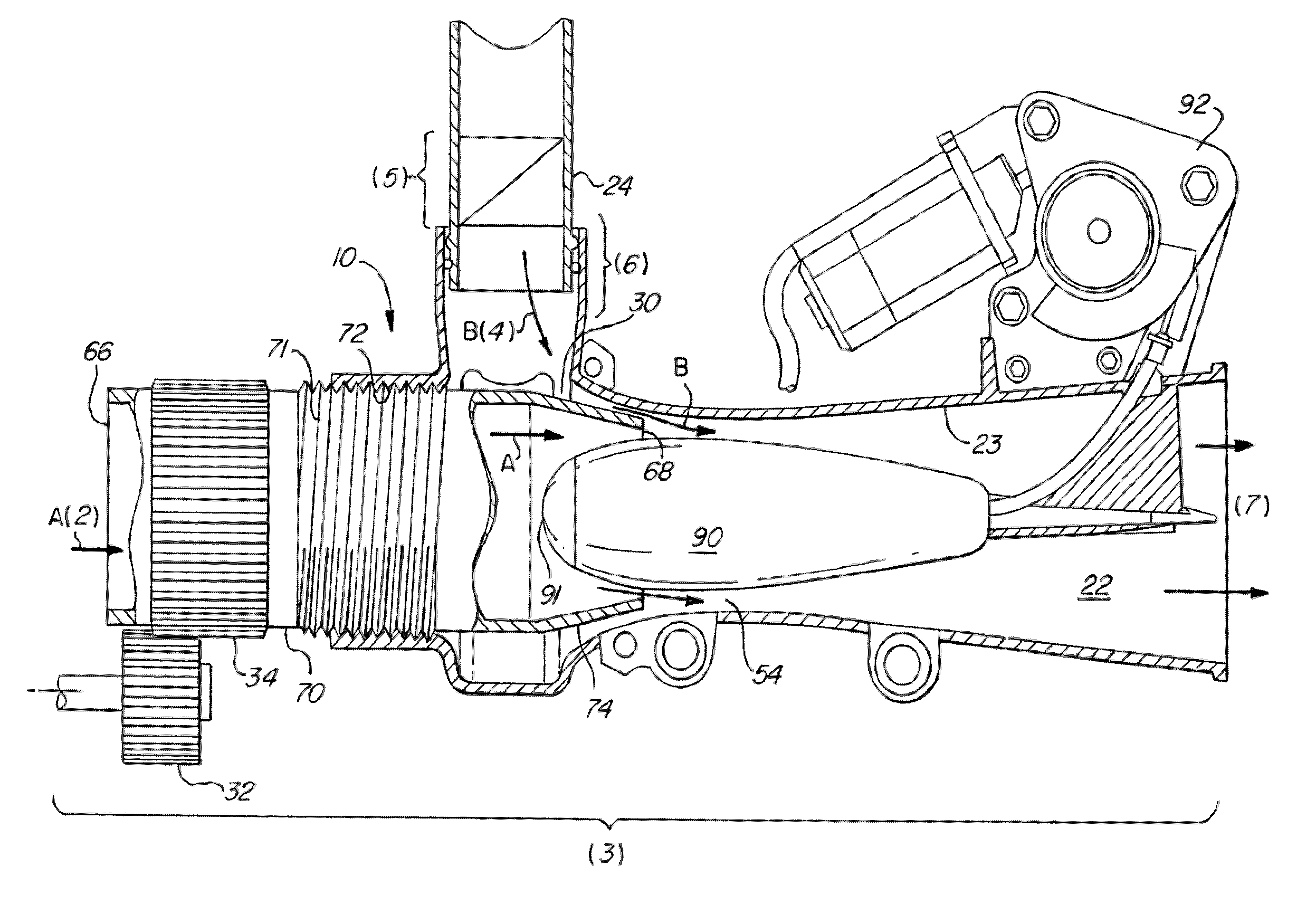
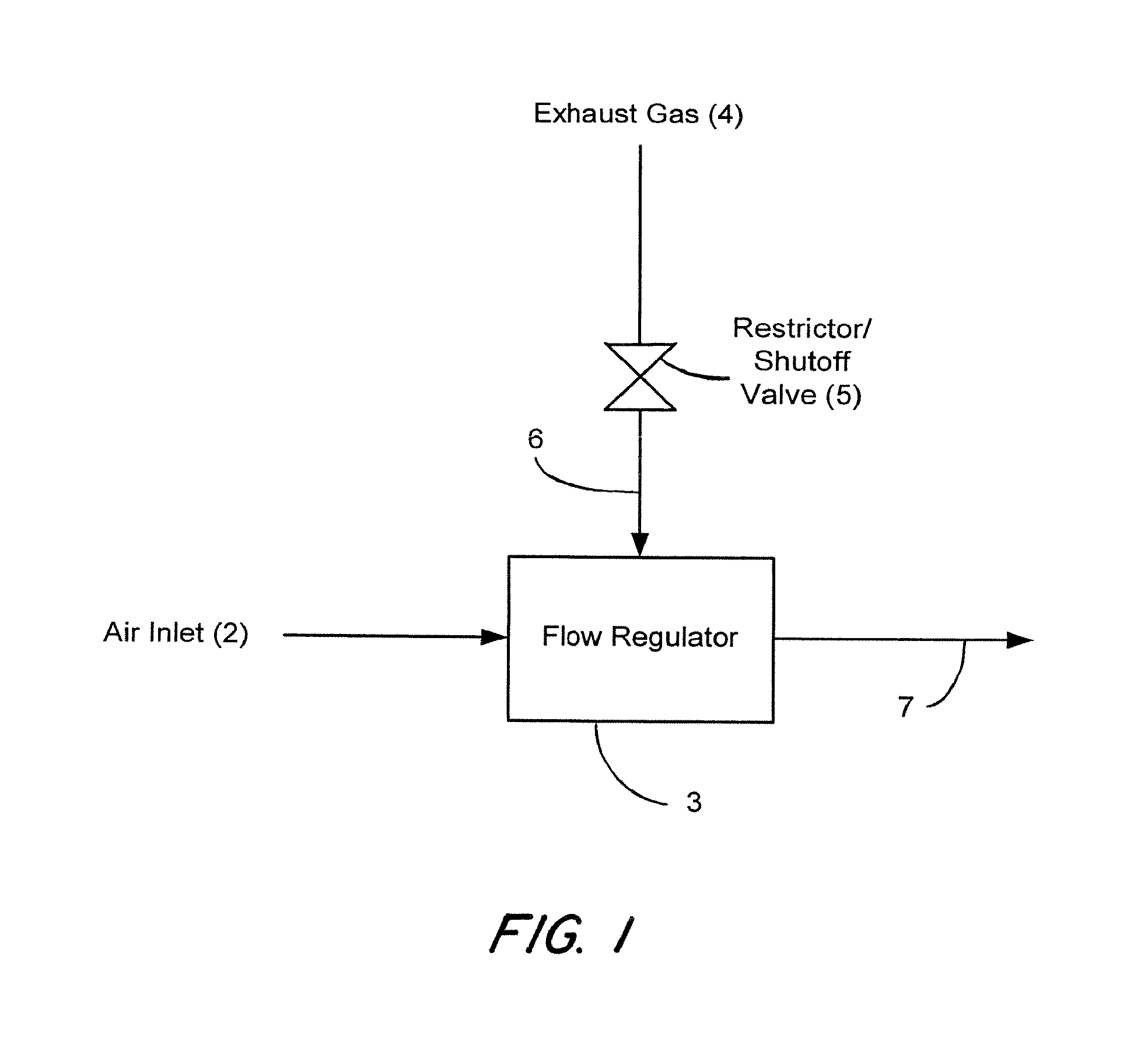
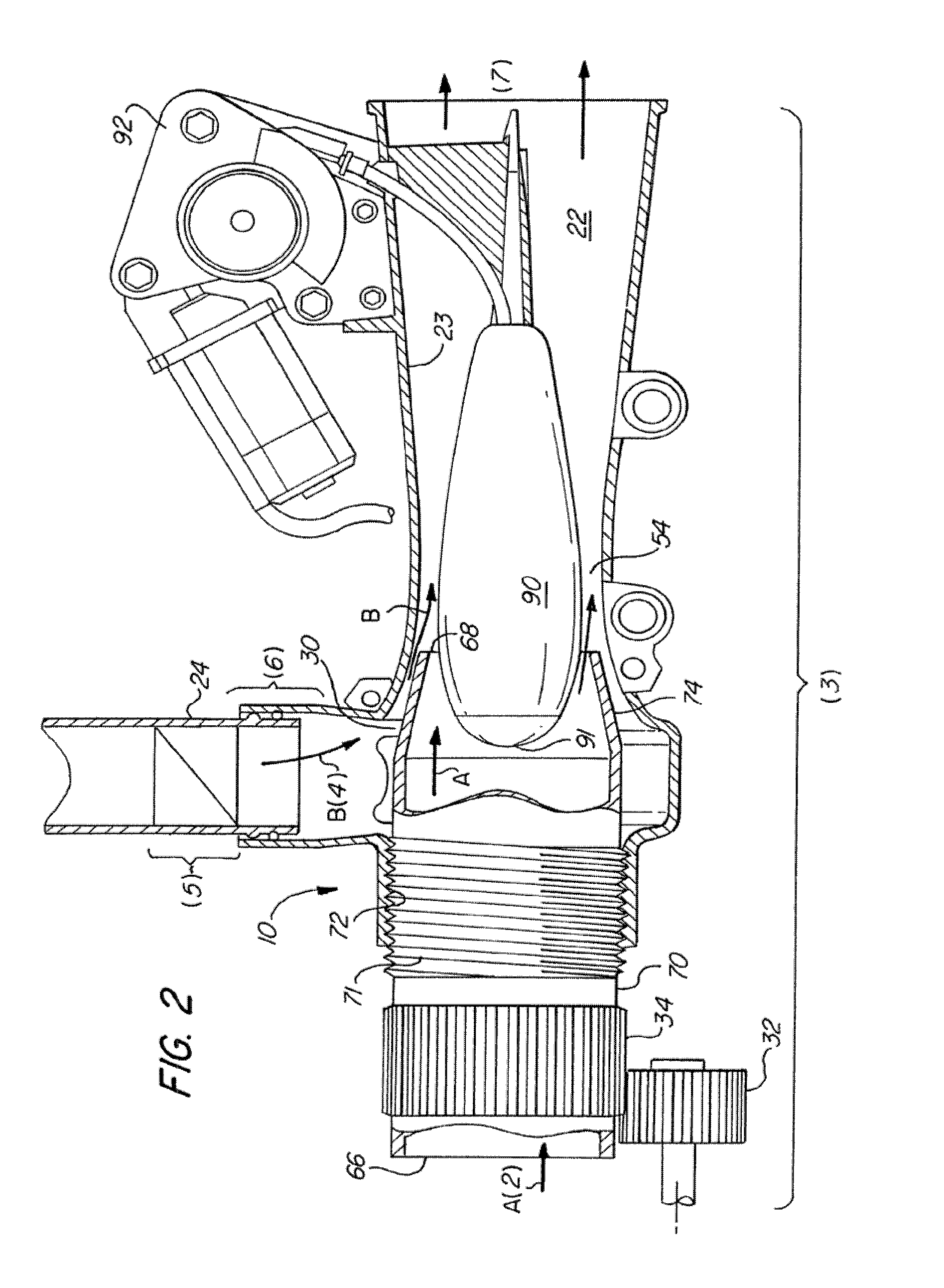
[0033]Referring now to FIG. 1, system 10 is illustrated. In FIG. 1, air inlet 2 is illustrated as coupled to flow regulator 3. Exhaust gas input 4 is fluidly coupled to restrictor / shutoff valve 5, which is also fluidly coupled 6 to flow regulator 3. Flow regulator 3 then receives both air inlet 2 and exhaust gas input 4 and outputs fluid flow 7 to. In this advantageous embodiment, flow regulator 3 operates in tandem with restrictor / shutoff valve 5 to variably control the flow of both air inlet 2 and exhaust gas input 4. For example, restrictor / shutoff valve 5 may be variably actuated to open / close so as to limit exhaust air flow to flow regulator 3.

[0034]In this particular embodiment, restrictor / shutoff valve 5 for the EGR system that is positioned upstream in the exhaust recirculation piping from flow regulator 3, so as to provide a stepwise control strategy. ...


PUM


Abstract

A system for controlling the mixture of an air flow and an exhaust gas flow utilizing two valves, the first valve at least partially positioned in an air intake conduit and regulating the flow of fluid through the air conduit, and the second valve positioned in an exhaust gas recirculation conduit for regulating the flow of exhaust gas. The control scheme presenting a sequential or stepwise control sequence, where the first valve is actuated over a first pressure range and the second valve is actuated over a second pressure range such that valves operate in a sequential manner.

Description

CROSS-REFERENCE TO RELATED APPLICATIONS[0001]This application claims the benefit of the filing date of U.S. Provisional Patent Application Ser. No. 60 / 703,480 filed Jul. 28, 2005.FIELD OF THE INVENTION[0002]The present invention relates to a system for controlling the mixture of an inlet air flow and an exhaust gas return flow in an engine. More specifically, the invention relates to a sequential control system for controlling the quantity of each flow.BACKGROUND OF THE INVENTION[0003]The expulsion of NOx by an internal combustion engine is typically controlled by limits established by local, state and federal governmental regulations. The formation of NOx constituents must therefore be maintained at least below some threshold limit or level. It is generally understood that the presence of NOx in the exhaust of internal combustion engines is determined by combustion temperature and pressure as well as by the air / fuel ratio (lambda). An increase in combustion temperature causes an in...

Claims


Application Information

Patent Timeline
Patent Type & Authority Patents(United States)
IPC IPC(8): F02M25/07F02B47/08
CPCF02D41/0065F02M25/0722F02M25/0745F02M25/0786F02M35/10118F02M35/10222F02D9/12F02D2009/0276F02D2041/0017Y02T10/47F02M26/39F02M26/19F02M26/64Y02T10/40F02D21/08F02B47/10
Inventor BERGGREN, GUSTAV
Owner HALDEX HYDRAULICS
Why Eureka
Try Eureka