Method and apparatus for monitoring and controlling laser intensity in a ROS scanning system

a laser intensity and ros scanning technology, applied in the direction of optical radiation measurement, instruments, photometry, etc., can solve the problem of not being able to take advantage of light emitted from the back fa

Inactive Publication Date: 2007-08-07
XEROX CORP
View PDF15 Cites 14 Cited by
  • Summary
  • Abstract
  • Description
  • Claims
  • Application Information

AI Technical Summary

Benefits of technology

[0010]One advantage of the present application is that none of the useful portion of the light beam is sacrificed for monitoring purpose. This effectively enables all useful portions of the light beam to be used by the ROS scanning system.
[0011]Another advantage of the present application is that the number of sources of error in the control system is reduced, thereby minimizing the power variability between multiple laser diodes.

Problems solved by technology

Therefore, it is not possible to take advantage of light being emitted from a back facet.

Method used


Image

  • Method and apparatus for monitoring and controlling laser intensity in a ROS scanning system
  • Method and apparatus for monitoring and controlling laser intensity in a ROS scanning system
  • Method and apparatus for monitoring and controlling laser intensity in a ROS scanning system

Examples


Embodiment Construction

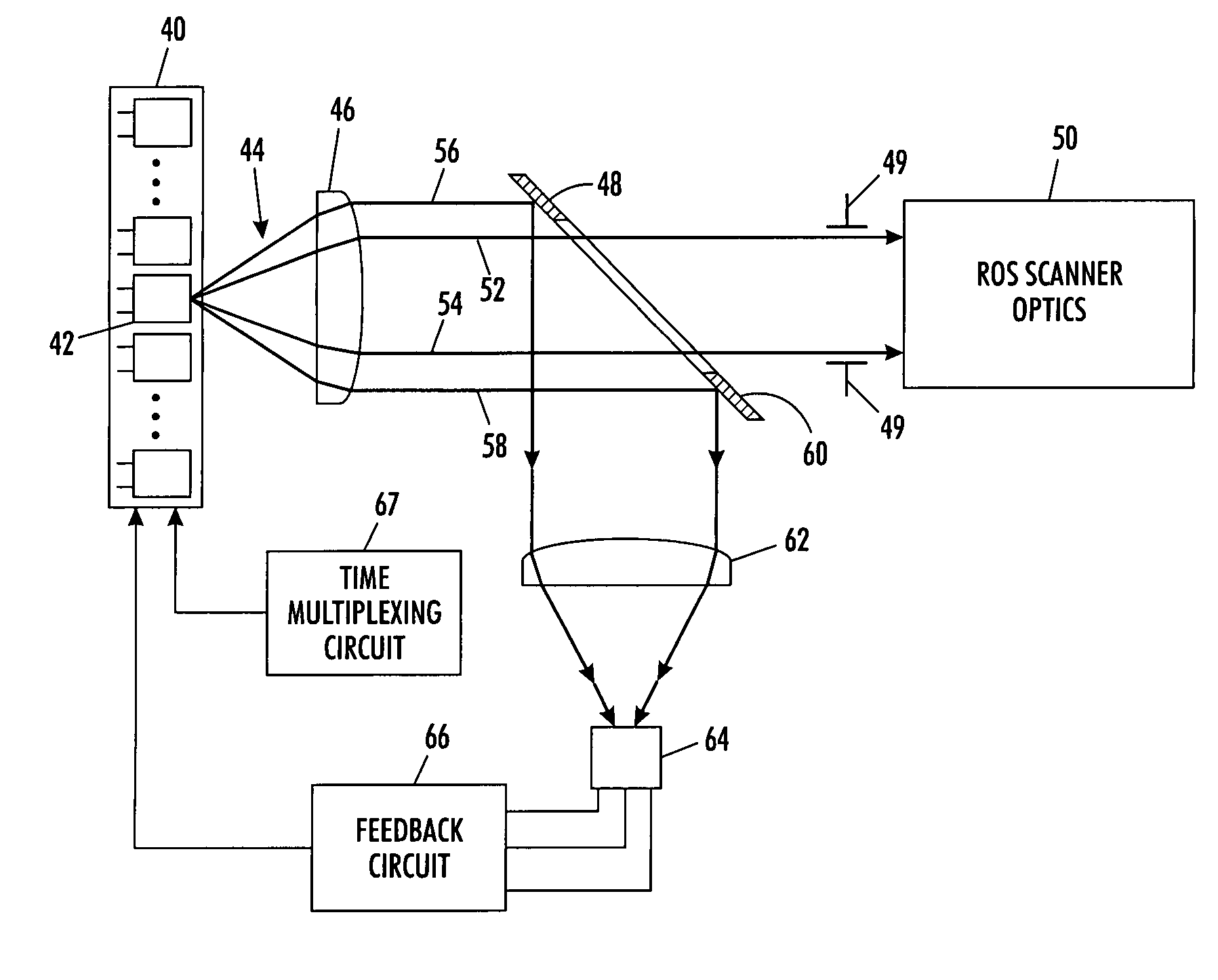
[0017]With reference to FIG. 1, there is shown in schematic form a raster scanning system of this application which is capable of monitoring the output power of individual VCSEL diodes. Included in the system, is a VCSEL diode array 40 having an array of VCSEL light sources 42. For the purpose of explaining the present application, however, explanation is provided with respect to only a single VCSEL light source 42, with the understanding the remaining VCSEL light sources are similarly controlled. The VCSEL array 40 is not limited with respect to shape or arrangement of diodes. In an exemplary embodiment, VCSEL array 40 includes 32 individual VCSEL light sources.

[0018]Upon receiving a driving current at its input terminals, the VCSEL light source 42 emits a light beam 44 which is collimated by collimating lens 46. Raster scanning systems typically include a limiting aperture to further define the beam 44 for use by the ROS scanner optics. For example, a limiting aperture may be used...


PUM


Abstract

A laser intensity monitoring and control apparatus and method. One or more laser diodes emit laser light at an intensity depending upon a supplied drive current. A collimating lens collimates the emitted laser light. An aperture clips portions of the collimated laser light striking the aperture outside the predetermined beam contour and reflects part or all of the clipped portion of the collimated laser light to a focusing lens. A monitoring detector senses the focused laser light and generates an electrical signal depending on the intensity of the focused laser light, wherein a feedback circuit monitors the electrical signal and adjusts the drive current of the laser diode as necessary to maintain a predetermined laser light intensity. A ROS scanner optics system receives and images the beam contour.

Description

BACKGROUND[0001]The present application relates generally to the monitoring of output power from a semiconductor laser diode, and more particularly to the monitoring of output power from a vertical cavity surfacing emitting laser (VCSEL) as used in a raster output scanning (ROS) system.[0002]It is well known in the scanning art to use laser diodes to generate a coherent laser beam which is then optically shaped for use as a scanning beam in a ROS system. It is also known to use multiple laser diodes to create multiple beams with each individual beam being independently modulated by video signals and scanned onto the recording or image surface as modulated beams. For these multiple beam applications, it has been found advantageous to use the rays with closely spaced laser diodes. Typically, the laser diodes in a multiple beam system are individually addressable. Individually addressable diodes require that each diode have a separate current source that drives or modulates the diodes....

Claims


Application Information

Patent Timeline
Patent Type & Authority Patents(United States)
IPC IPC(8): G01J1/32
CPCG01J1/04G01J1/0414G01J1/32G01J1/4257
Inventor ERNST, STEVEN L.
Owner XEROX CORP
Why Eureka
Try Eureka