
Floating gate with unique profile by means of undercutting for split-gate flash memory device

a technology of flash memory device and floating gate, which is applied in the direction of semiconductor devices, electrical devices, transistors, etc., can solve the problems of unwanted low rtv, and the etching process always rounds the corner edge of the floating gate to get unwanted high ftv

Inactive Publication Date: 2007-08-07
TAIWAN SEMICON MFG CO LTD
View PDF4 Cites 28 Cited by
  • Summary
  • Abstract
  • Description
  • Claims
  • Application Information

AI Technical Summary

Benefits of technology

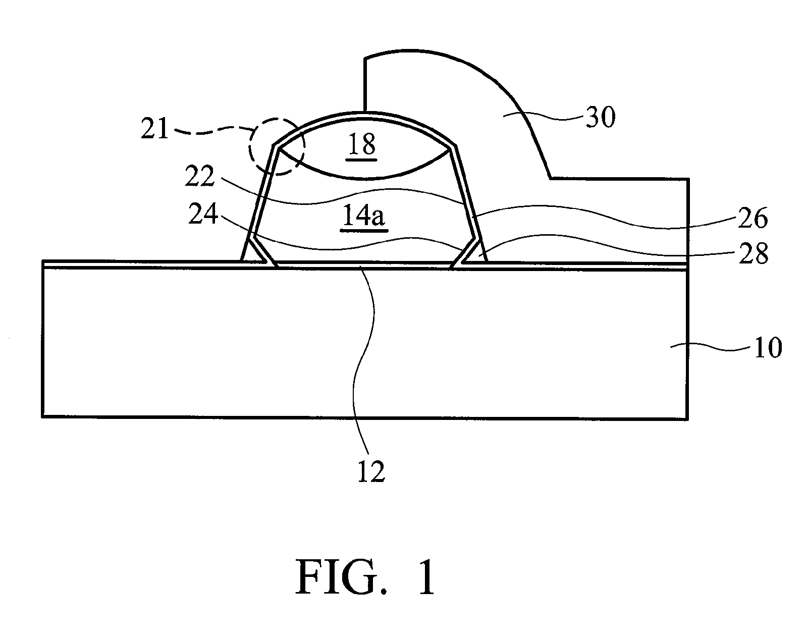
[0003]As known in split-gate flash technology, forward-tunneling voltage (FTV) and reverse-tunneling voltage (RTV) are highly correlated to the floating gate profile. Also, RTV is correlated to a tiny nitride spacer formed between the lower edges of the floating gate and the control gate. This nitride spacer, also called a reverse-tunneling nitride (RTN) spacer, is used to prevent write disturbance caused by reverse tunneling. Thus, how to control the profile of the floating gate and maintain the film thickness of the RTN spacer are important issues for improving program and erasure performance. In one case of fabricating a floating gate with a tapered profile, a sharp tip at the corner edge of the floating gate is obtained to achieve desired low FTV. However, this tapered profile usually accompanies a thin RTN spacer since it is difficult to control the process of etching a nitride spacer on the slanted sidewall, causing unwanted low RTV. Comparatively, in another case of fabricating a floating gate with a vertical profile, a thicker RTN spacer is obtained to achieve desired high RTV, but the later etching process always rounds the corner edge of the floating gate to get unwanted high FTV for lack of the sharp poly-tip.

Problems solved by technology

Thus, how to control the profile of the floating gate and maintain the film thickness of the RTN spacer are important issues for improving program and erasure performance.
However, this tapered profile usually accompanies a thin RTN spacer since it is difficult to control the process of etching a nitride spacer on the slanted sidewall, causing unwanted low RTV.
Comparatively, in another case of fabricating a floating gate with a vertical profile, a thicker RTN spacer is obtained to achieve desired high RTV, but the later etching process always rounds the corner edge of the floating gate to get unwanted high FTV for lack of the sharp poly-tip.

Method used


Image

  • Floating gate with unique profile by means of undercutting for split-gate flash memory device
  • Floating gate with unique profile by means of undercutting for split-gate flash memory device
  • Floating gate with unique profile by means of undercutting for split-gate flash memory device

Examples


Embodiment Construction

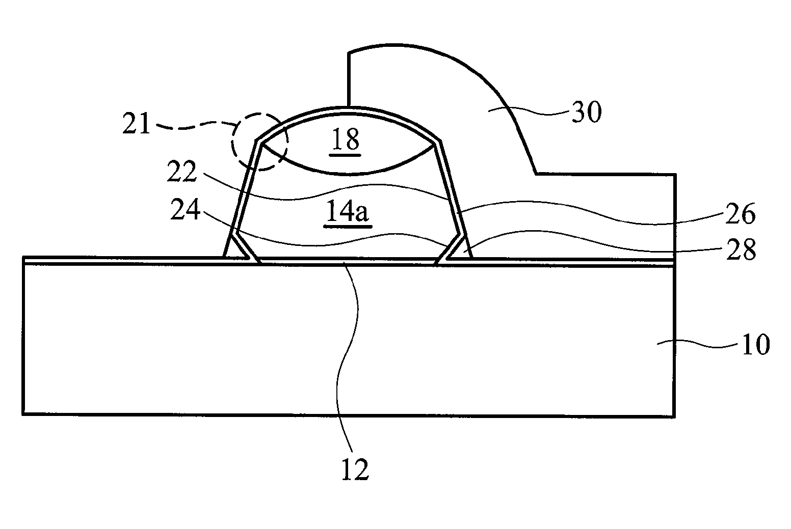
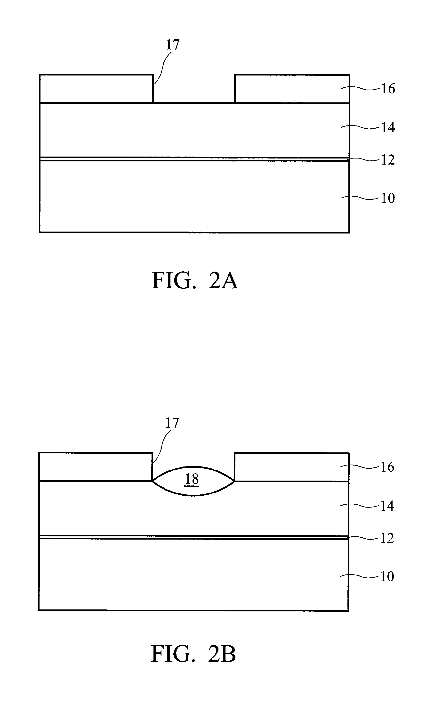
[0014]Preferred embodiments of the present invention provide a floating gate with a lateral recess adjacent to its bottom edge and a dielectric spacer formed in the lateral recess between the floating gate and a control gate for a split-gate flash memory device. The inventive method of fabricating the same can be easily achieved by adding an undercutting step for forming the lateral recess, which is compatible with the existing floating gate process in spit-gate flash technology. The lateral recess by means of undercutting the floating gate profile can ensure a thick and sustainable spacer formed therein to prevent inadvertent reverse tunneling between the floating gate and the control gate, obtaining high RTV. It is also preferred that the sidewall portion of the floating gate, except for the lateral recess, has a slope which can achieve a sharp tip at the top corner edge of the floating gate to obtain low FTV. This unique profile of the floating gate, including a tapered profile c...


PUM


Abstract

A split-gate flash memory device has a floating gate with a lateral recess at its bottom sidewall by adding an undercutting step. The split-gate flash memory device has a floating gate with a lateral recess on a substrate, an integrated dielectric layer lining the substrate, the sidewall and the lateral recess of the floating gate; a control gate on the integrated dielectric layer and covering at least part of the floating gate; and a dielectric spacer in the lateral recess between the integrated dielectric layer and the control gate.

Description

TECHNICAL FIELD[0001]The present invention relates to split-gate flash memory devices, and particularly to a floating gate with a unique profile by means of undercutting for a split-gate flash memory device.BACKGROUND[0002]Flash memory device is a non-volatile memory device capable of maintaining information stored in its memory cell without a power supply. One advantage of the flash memory device is its capacity for block-by-block memory erasure, and another advantage is its low electric consumption. The flash memory device can be classified into a stacked-gate cell, a split-gate cell, and the like, according to their corresponding cell transistor gate structures. A split-gate cell which includes a control gate physically implemented laterally adjacent to a floating gate is characterized by excellent efficiency in its erasure and program functionality. This high efficiency effectively protects the split-gate cell from inadvertent over-erasure of stored data.[0003]As known in split-...

Claims


Application Information

Patent Timeline
Patent Type & Authority Patents(United States)
IPC IPC(8): H01L29/788H10B69/00
CPCH01L21/28273H01L29/42324H01L29/40114
Inventor LIU, SHIH-CHANGLO, CHI-HSINTSAI, CHIA-SHIUNGHO, CHI-WEI
Owner TAIWAN SEMICON MFG CO LTD
Learn More