One-magnet rectangular transducer

a rectangular, transducer technology, applied in the direction of the transducer casing/cabinet/support, the telephone set construction, the telephone set with user guidance/features, etc., can solve the problems of linear and nonlinear distortion, distorted distribution of the magnetic field along the gap, and requiring a considerable building height, etc., to achieve low distortion, simple magnetic field, and high quality

Inactive Publication Date: 2007-08-07
GETTOP EURO R&D
View PDF23 Cites 87 Cited by
  • Summary
  • Abstract
  • Description
  • Claims
  • Application Information

AI Technical Summary

Benefits of technology

[0039]The second aspect of the invention enables a fundamentally very compact and simple transducer. Therefore, the transducer is also very well suited for miniature applications such as mobile phones and hearing aids. In addition, the design of the magnetic circuit results in a simple magnetic field in the gap with flux lines perpendicular to the gap. Therefore, the design is fundamentally insensitive to small imperfections due to production tolerances. This property makes the design suited for applications requiring high quality transducers with low distortion in combination with low production costs.

Problems solved by technology

If the inner and outer members defining the gap are not perfectly coaxial, the gap will not have a uniform width resulting in a distorted distribution of the magnetic field along the gap.
A coil carrying electric currents at audio frequencies in such a distorted magnetic field will tend not to move in a linear movement but rather to tilt, which causes linear and nonlinear distortion.
Another disadvantage of traditional transducers with ring-shaped magnetic gap is related to the fact that they require a considerable building height since the magnetic circuit requires a bottom piece.
For applications in miniature equipment, such as hearing aids or mobile phones, the dimensions of each component is a crucial parameter whereby the use of traditional transducers with ring-shaped gaps within e.g. hearing aids becomes a very difficult task.

Method used


Image

  • One-magnet rectangular transducer
  • One-magnet rectangular transducer
  • One-magnet rectangular transducer

Examples


Embodiment Construction

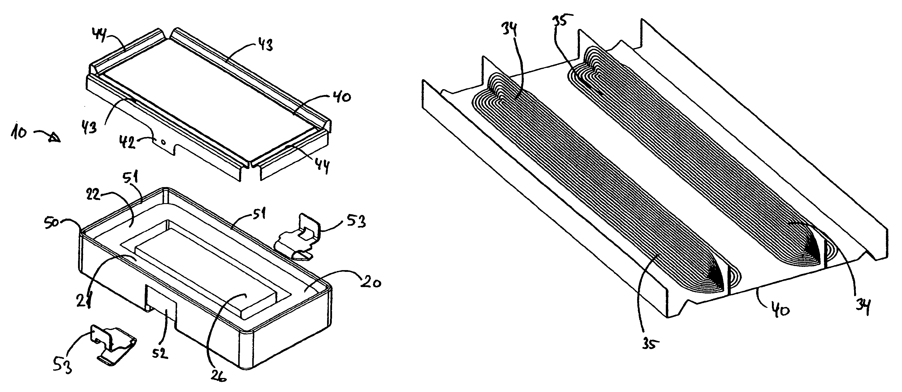
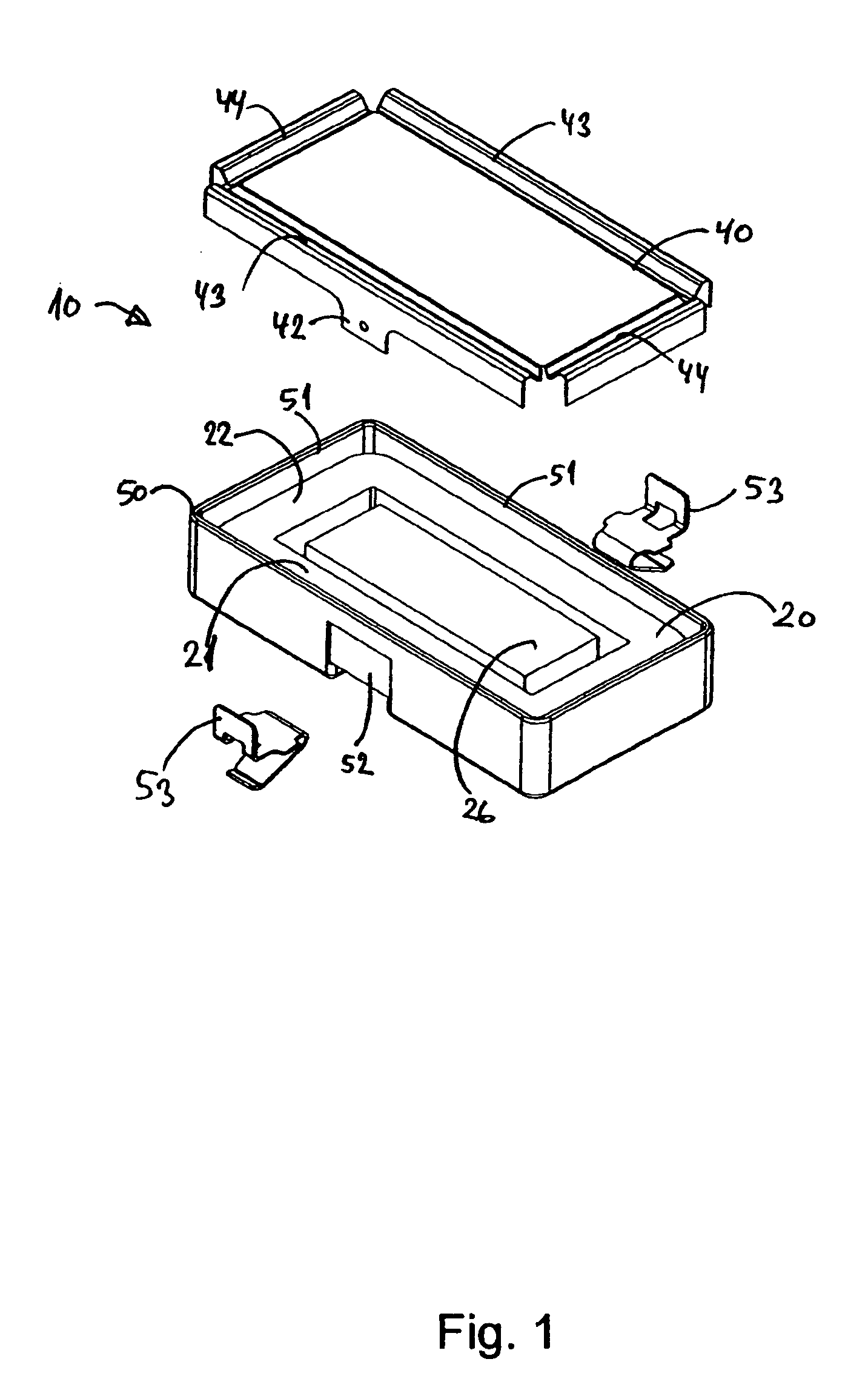
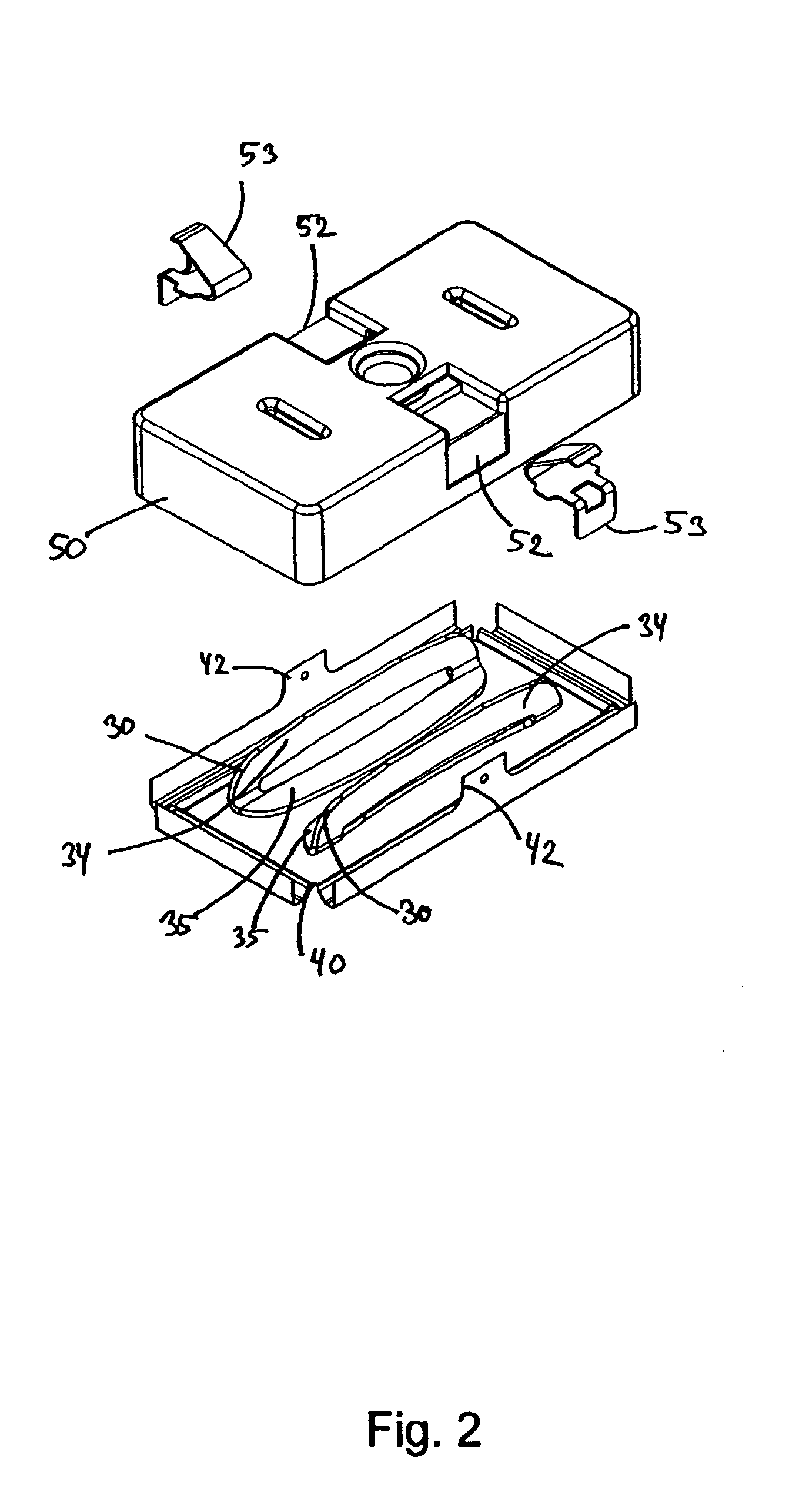
[0065]FIGS. 1 and 2 show a transducer 10 according to the first aspect of the invention with its main components: a magnetic circuit 20, a coil system 30 and a diaphragm 40. FIG. 3 also shows the magnetic circuit 20.

[0066]As is best seen in FIG. 3, the magnetic circuit 20 has two long legs 21 and two short legs 22 connected at their ends to form a ring of generally rectangular shape, thus forming a rectangular through-going opening 24. The two long legs 21, the two short legs 22 are of a magnetically soft material preferably having a high magnetic saturation value. The surfaces 25 of the two long legs 21 facing towards the opening 24 are generally plane and define a gap there between. A magnet 26 is fixed in the centre of the opening in such a way that it is not in direct contact with the magnetically conductive material. The two poles of the magnet 26 are directed towards each of the long legs 21 thus defining gaps 28 between the magnetic pole surfaces 29 and the surfaces 25 of the...


PUM


Abstract

An electroacoustic transducer comprising a magnetic circuit of a magnetically conductive material with a pair of opposed surfaces defining a gap there between, the magnetic circuit comprising one magnet. The magnet can either be positioned in the center of the magnetically conductive material so as to form two gaps. In an alternative embodiment the magnet is attached to the magnetic conductive material forming only one gap. The transducer further comprises a diaphragm and a coil system having electrically conducting paths fastened to the diaphragm. The coil system has portions of its paths situated in the gap. The transducer may be supplied with an additional diaphragm and coil system positioned on the opposite side of the magnetic circuit. In a preferred embodiment the transducer is rectangular. The transducer is suited for integration into miniature components such as mobile communication equipment and hearing aids. Embodiments of the transducer are suited for side-firing or side-shooting applications such as in mobile phones.

Description

FIELD OF THE INVENTION[0001]The present invention relates to electroacoustic transducers, in particular to electroacoustic transducers with magnetic circuits having through-going openings carrying permanent magnets so as to generate magnetic field in one or two gaps within the openings of the magnetic circuit.BACKGROUND OF THE INVENTION[0002]Electroacoustic transducers, and in particular electrodynamic transducers, are widely used in telecommunications equipment such as wired and mobile telephones, where small size is a requirement. Traditional electrodynamic microphones and loudspeaker transducers used in e.g. mobile telephones are rotational symmetric and have a circular disc or ring-shaped permanent magnet, which is magnetised in the axial direction of the magnet. A magnetic circuit of magnetically soft iron or other suitable material define a ring-shaped gap with a radially oriented magnetic field generated by the magnet. A diaphragm carries a ring-shaped coil of electrically co...

Claims


Application Information

Patent Timeline
Patent Type & Authority Patents(United States)
IPC IPC(8): H04R1/00H04R1/02H04R11/02H04R9/06H04M1/03H04M1/247H04R9/02H04R7/04H04R7/12H04R9/00H04R9/04
CPCH04M1/03H04R7/12H04R9/047H04R7/06
Inventor JOHANNSEN, LEIFANDERSEN, MORTEN KJELDSENJENSEN, FINN
Owner GETTOP EURO R&D
Why Eureka
Try Eureka