Gap sub assembly

a sub-assembly and gap technology, applied in the direction of fluid removal, drilling accessories, borehole/well accessories, etc., can solve the problems of loss of electric discontinuity, severe compressive and tensile stress on the assembly, etc., to resist the tensional and compressive stress, the effect of absorbing the make-up torqu

Active Publication Date: 2007-08-14
PHOENIX TECH SERVICES LP
View PDF9 Cites 46 Cited by
  • Summary
  • Abstract
  • Description
  • Claims
  • Application Information

AI Technical Summary

Benefits of technology

[0015]Preferably, the woven fabric is formed of poly(p-phenyleneterephtalamide), a material which is sold commercially under the registered trade-mark KEVLAR™. Such fabric has been shown to be capable of withstanding the make-up torque applied when threading together the two subs. It also has been shown to withstand the tensional and compressive stresses which arise when incorporated into an operational drill string. And finally, it is effective to provide electrical discontinuity.

Problems solved by technology

The assemblies are subject to severe compressive and tensile stresses in use.
The brittle ceramic coatings tend to crack and chip, thereby leading to loss of the electric discontinuity.
And the Teflon™ coating may extrude during use, leading to the same result.

Method used


Image

  • Gap sub assembly
  • Gap sub assembly
  • Gap sub assembly

Examples


Embodiment Construction

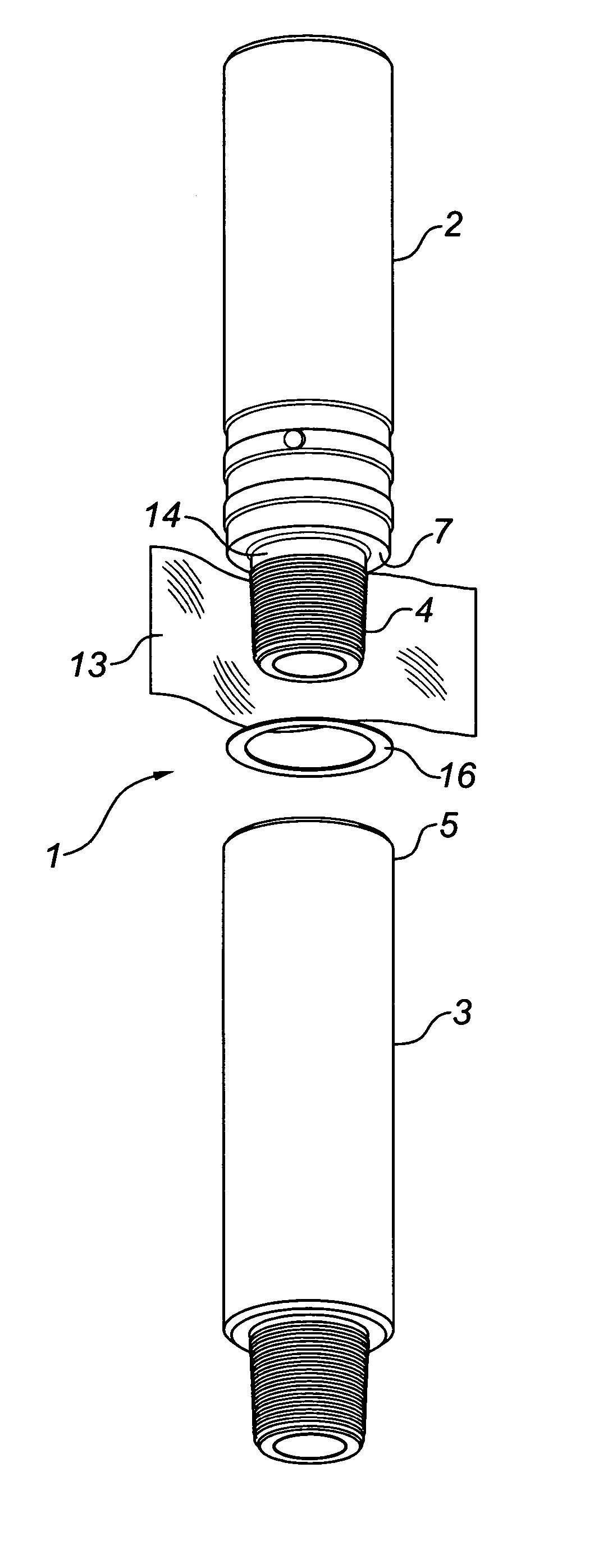
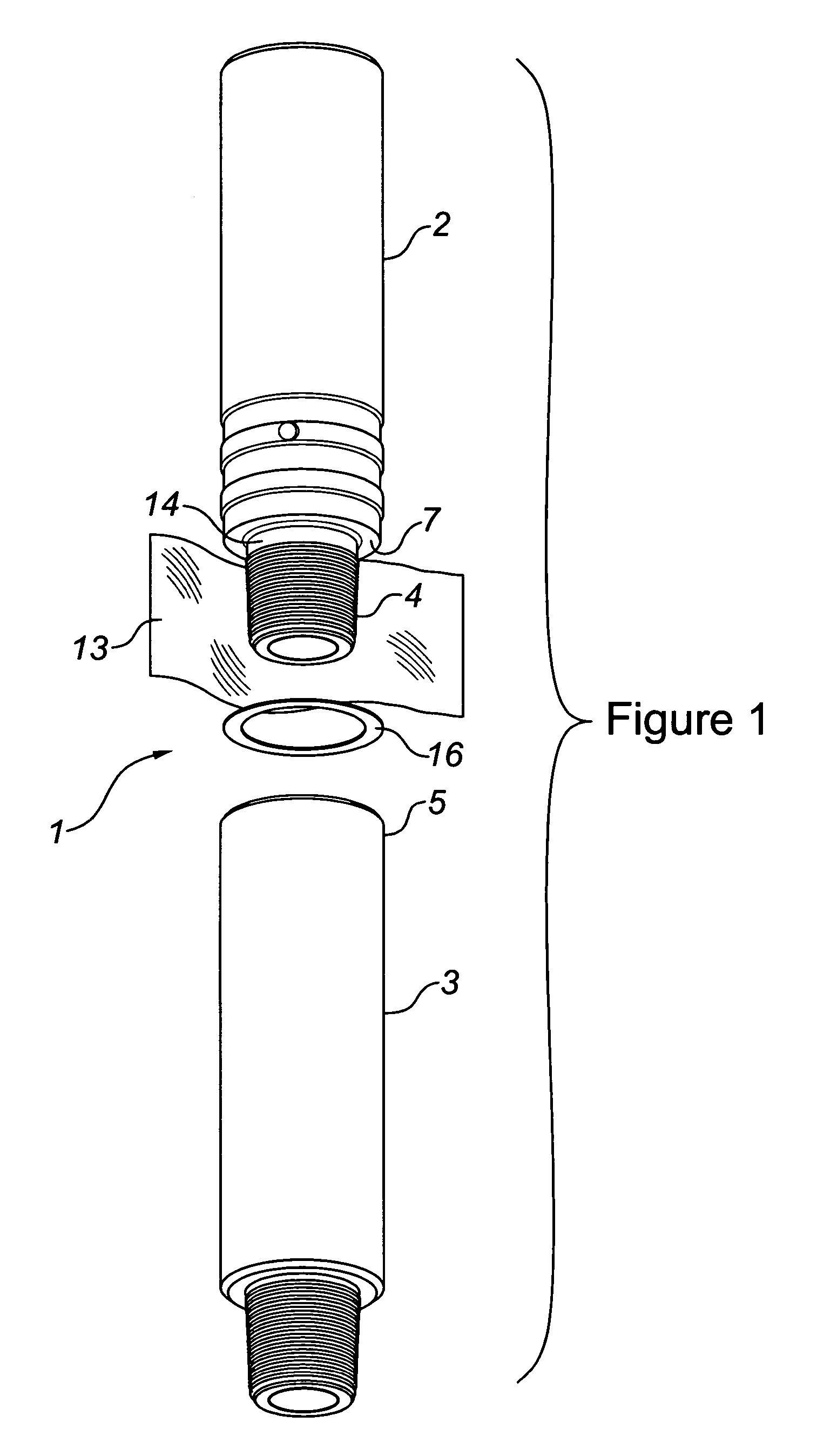
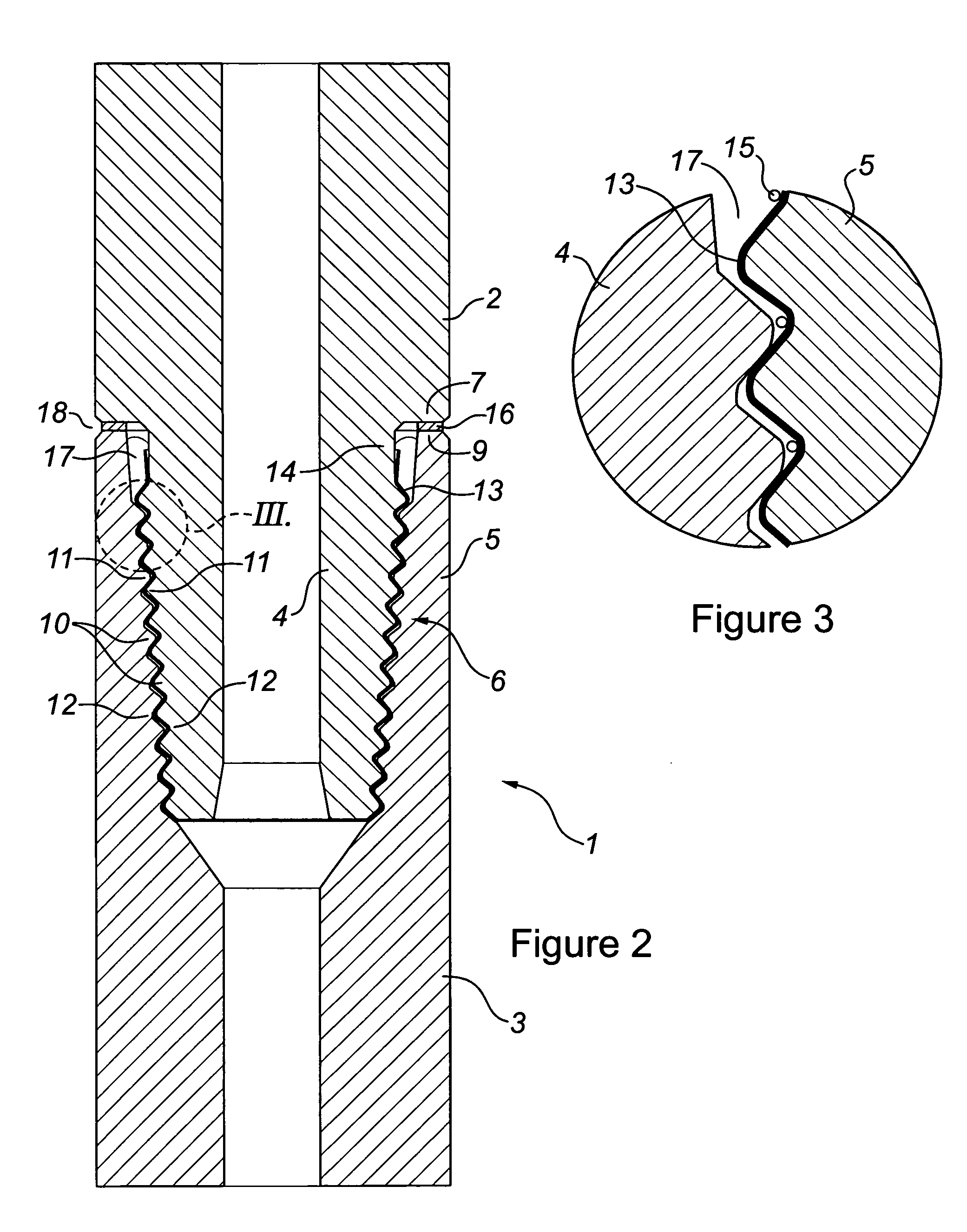
[0021]Having reference to the Figures, there is provided a gap sub assembly 1 comprising a pair of tubular, steel pipe subs 2,3. Each sub 2,3 has a threaded pin 4 and box 5 at its ends. When assembled, the pin 4 of one sub 2 is threadably connected with the box 5 of the other sub 3 to form a connection 6 joining the subs end to end. At the connection 6, the sub 2 has a shoulder 7 forming an annular face 8 and the box 5 of the sub 3 has an annular end face 9.

[0022]The pin 4 and box 5 of each sub 2,3 are machined to form tapered threads 10, such as Hughes H-90™ threads, having crests 11 and trough 12. The connection pin 4 is machined to standard dimensions. The connection box 5 is machined slightly oversize to allow room for the layer 13 of KEVLAR™ woven fabric. Cutting the connection box threads 0.007″ deeper for a 0.005″ thick fabric layer 13, is suitable.

[0023]The fabric layer 13 is dimensioned to completely cover the connection pin threads 10 with minimal overlap. The fabric layer...


PUM


Abstract

The gap sub assembly comprises a pair of electrically conductive subs. Each sub has a threaded pin and box. A pin and box are threaded together to form a connection. An electrically insulating, woven fabric overlies and conforms with the threads of the connection pin. An electrically insulating, annular washer separates the seal faces of the connection. The assembly functions to provide an electrical discontinuity when incorporated into a conductive drill string.

Description

FIELD OF THE INVENTION[0001]The present invention relates to an electrically insulating gap sub assembly for use in a drill string. The gap sub assembly functions to block current flow through the drill string.BACKGROUND OF THE INVENTION[0002]It is known in oilfield drilling technology to provide an assembly, at the lower end of a drill string drilling a wellbore, for transmitting downhole data, measured by sensors, to a receiver at ground surface. This transmission is done by means of electric signals passing upwardly through the formation penetrated by the wellbore.[0003]For example, it is known to measure the inclination and direction of the wellbore adjacent the bit using an EMT tool. The EMT tool includes a signal generating unit spaced behind the drill bit. This unit produces alternating current signals indicative of the measurements taken by downhole sensors.[0004]In conjunction with the signal generating unit it is necessary to provide, in the drill string, a device that wil...

Claims


Application Information

Patent Timeline
Patent Type & Authority Patents(United States)
IPC IPC(8): E21B17/02
CPCE21B17/028E21B17/0285
Inventor CRAMER, DAVID
Owner PHOENIX TECH SERVICES LP
Why Eureka
Try Eureka