Hybrid drive system and vehicle equipped therewith

Active Publication Date: 2007-08-14
AISIN AW CO LTD +1
View PDF54 Cites 59 Cited by
  • Summary
  • Abstract
  • Description
  • Claims
  • Application Information

AI Technical Summary

Benefits of technology

[0014]Generally in the foregoing hybrid drive system, the first motor is controlled such that the power distribution planetary gear is kept to have a relatively high gear ratio (an overdrive state), and the engine is controlled so as to be in a state where the efficiency is high and the exhaust gas amount is small (so as to follow the optimum fuel consumption characteristics in general). When acceleration is required at a time of starting or in o

Problems solved by technology

This may cause a problem in vehicle mountability, p

Method used


Image

  • Hybrid drive system and vehicle equipped therewith
  • Hybrid drive system and vehicle equipped therewith
  • Hybrid drive system and vehicle equipped therewith

Examples


first embodiment

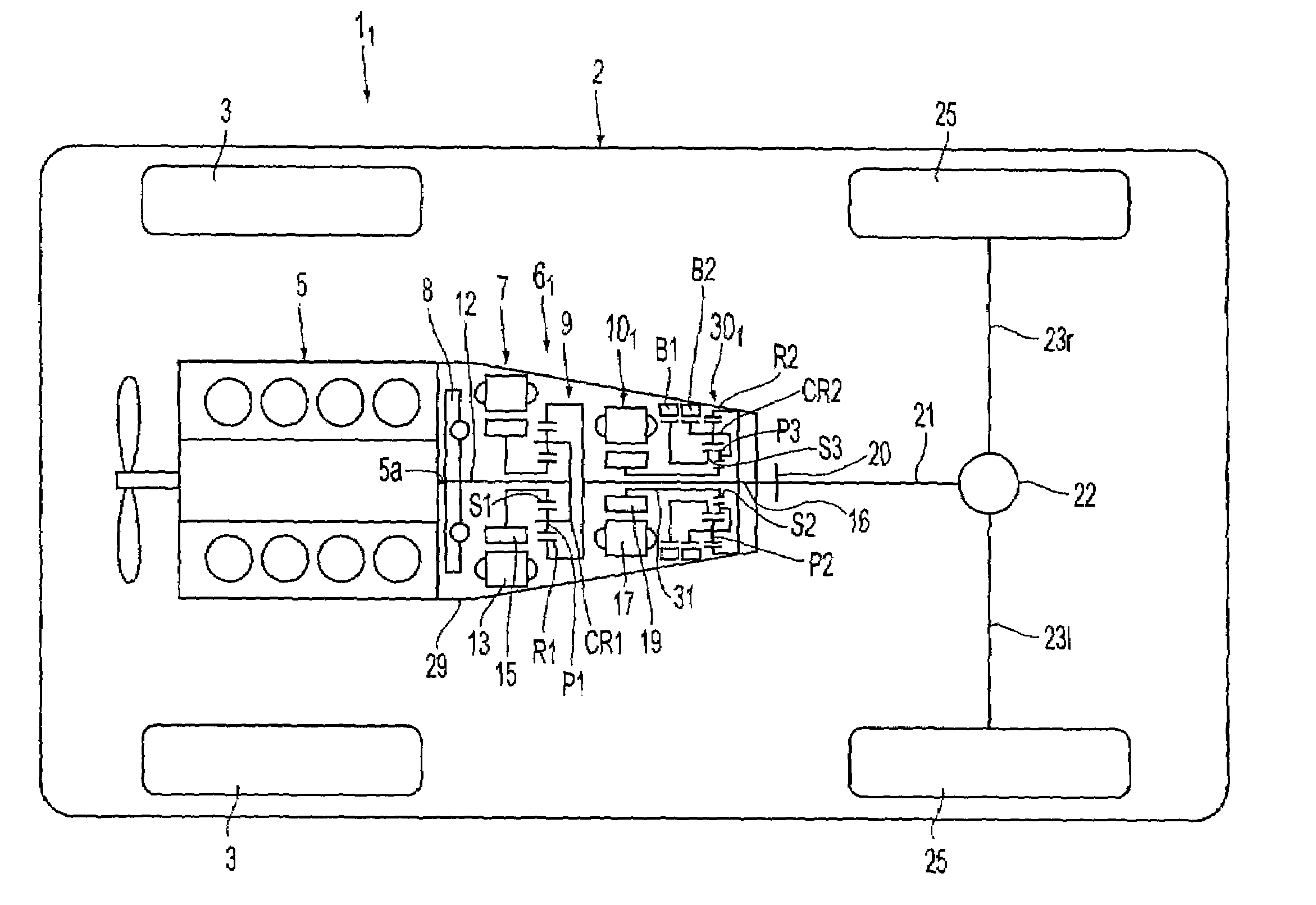
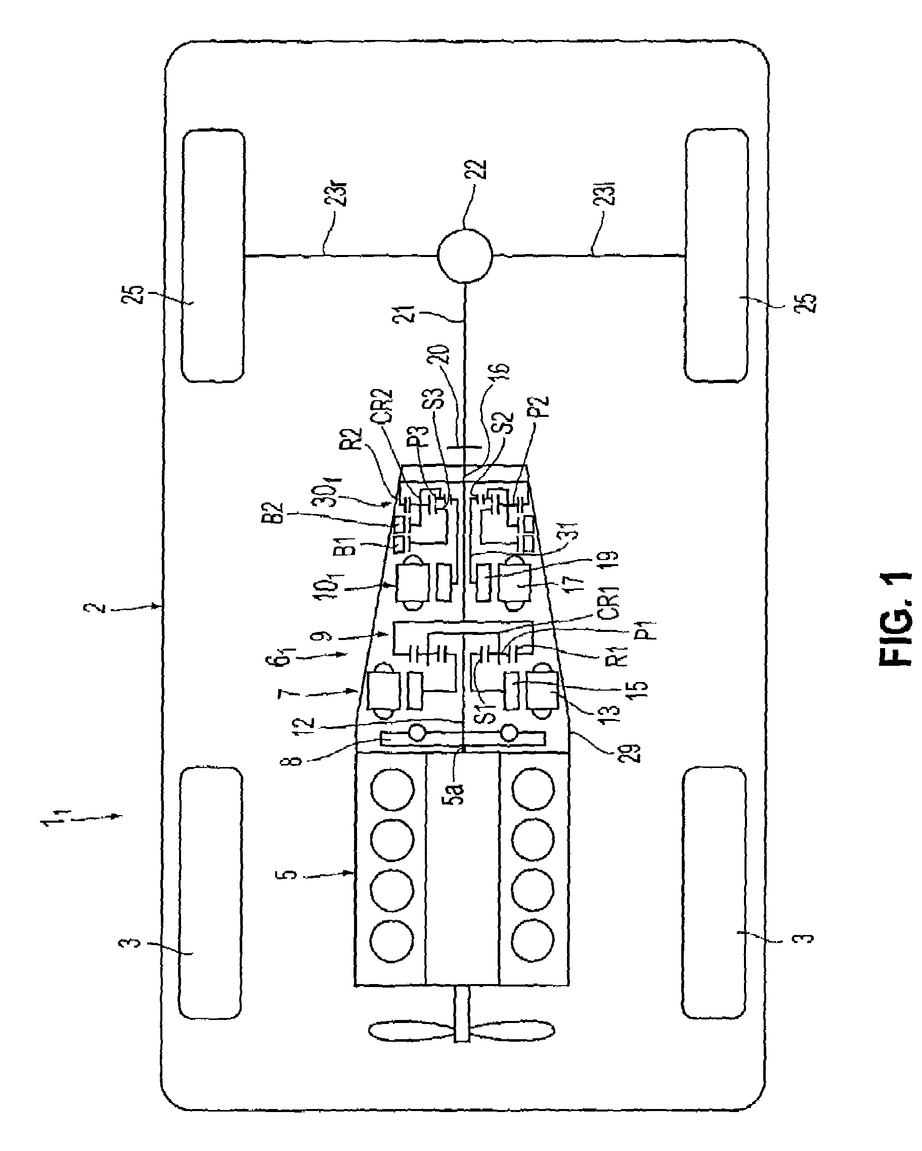
[0046]FIG. 1 is a plan view illustrating an outline of an FR-type vehicle equipped with a hybrid drive system (a first embodiment) according to the invention, in which reference numeral 11 denotes the FR-type vehicle equipped with the hybrid drive system 61. A vehicle body 2 of the vehicle 11 is suspended to right and left front wheels 3, 3 and right and left rear wheels 25, 25. In the front part of the vehicle body 2 is an internal combustion engine 5 with the crank shaft that is oriented in the longitudinal direction and is mounted via a rubber mount.

[0047]As in the case of the foregoing, the hybrid drive system 61 has a first motor (electric motor for control) 7, a power distribution planetary gear 9, and a second motor (electric motor for drive) 101 which are axially arranged and aligned with the crank shaft, in order, from the engine 5 side. In addition, a transmission 301, such as an automatic transmission or the like, is arranged behind the second motor 101. The hybrid drive ...

second embodiment

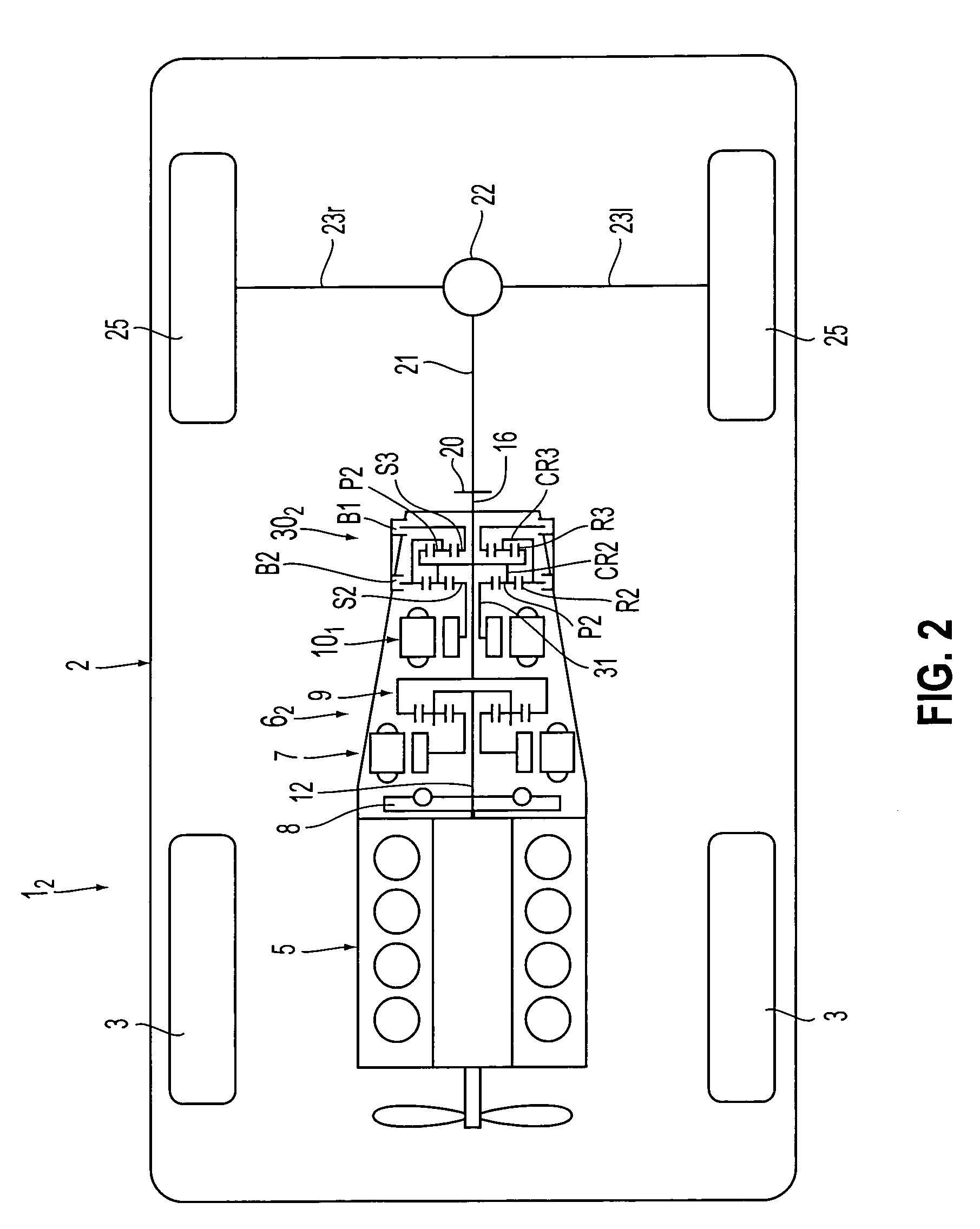
[0065]A transmission 302 of a hybrid drive system 62 (a second embodiment), shown in FIG. 2, includes two simple planetary gears in which the carriers and ring gears are connected each other. A first sun gear S2 is connected with a sleeve shaft 31 which serves as an input shaft of the transmission. A first carrier CR2 and a second ring gear R3, which are connected with each other, are connected with the output shaft 16. Further, a first ring gear R2 and a second carrier CR3, which are connected with each other, are connected with a second brake B2. A second sun gear S3 is connected with a first brake B1.

[0066]The transmission 302 is provided for executing a two-step speed change with different reduction gear ratios. In a low state, the second brake B2 is engaged and the first brake B1 is in a released state. In this state, the output of the second electric motor (motor for drive) 101 is transmitted to the first sun gear S2 via the sleeve shaft 31. Then, based on a state where the ri...

third embodiment

[0075]FIG. 7 is a sectional view specifically illustrating the transmission 303 described above in FIG. 3. The transmission 303 is provided with a so-called Ravigneaux-type planetary gear unit PU which includes a single dual planetary gear (S2, R2, CR2) and a planetary gear having a sun gear S3 and the common carrier CR2 having a long pinion P2 common with the planetary gear. Also, the long pinion P2 is shaped in a stepped manner with different number of teeth. In other words, the dual planetary gear above includes the first sun gear S2, the first ring gear R2 and the common carrier CR2 supporting the short pinion P3 and the long pinion P2, in which the short pinion P3 meshes with the sun gear S2 and the ring gear R2, and the small-diameter gear P2b of the long pinion P2 meshes with the short pinion P3 above. The large-diameter gear P2a of the long pinion P2 above meshes with the second sun gear S3.

[0076]The first sun gear S2 is integrally formed with the sleeve shaft (intermediate...


PUM


Abstract

An output of an internal combustion engine is transmitted to an output shaft by controlling a control motor to change a rotation speed output from the engine without speed steps via power distribution planetary gear. An output of a drive motor is input to the output shaft by changing the speed into two-step decelerated rotation by means of an automatic transmission. The transmission produces a desired torque by decelerating the speed by a large degree when a vehicle speed is low, and produces a desired number of revolutions by decelerating the speed by a small degree when the vehicle speed is high.

Description

INCORPORATION BY REFERENCE[0001]The disclosure of Japanese Patent Application No. 2002-226765 filed on Aug. 2, 2002 including the specification, drawings and abstract are incorporated herein by reference in its entirety.BACKGROUND OF THE INVENTION[0002]1. Field of Invention[0003]This invention relates to a hybrid drive system incorporated in a vehicle and a vehicle equipped with the hybrid drive system, and more specifically, to an output structure from a drive (assist) electric motor.[0004]2. Description of Related Art[0005]Conventionally, a hybrid drive system of a so-called mechanical distributing type (a distribution type or a two motor type) has been provided in a vehicle (registered trademark name “PRIUS”) for commercial practice, in which the engine output is distributed in a planetary gear to a control motor and to a traction output side, and the motor is controlled mainly as a generator for step-less control of the output torque of the planetary gear, and torque of another ...

Claims


Application Information

Patent Timeline
IPC IPC(8): B60K1/02B60K6/365B60K6/40B60K6/445B60K6/54B60K6/547B60K17/04B60L50/16F16H3/62F16H3/72F16H57/02F16H57/023
CPCB60K6/365B60K6/40B60K6/445B60K6/547F16H3/728B60K1/02Y10T477/23F16H2037/0873Y10S903/911Y02T10/6239Y10T477/26F16H3/727Y02T10/62B60K17/04
Inventor WAKUTA, SATORUOMOTE, KENJIINUZUKA, TAKESHIOZAKI, KAZUHISATSUKAMOTO, KAZUMASAYAMAGUCHI, KOZOADACHI, MASATOSHIMOTOIKE, KAZUTOSHIKOJIMA, MASAHIRO
Owner AISIN AW CO LTD
Why Eureka
Try Eureka