Optical unit and projection-type image display apparatus using the same

a technology of optical units and projection-type images, applied in the direction of instruments, polarising elements, projectors, etc., can solve the problems of reducing the extinction ratio, reducing the extinction speed, and the effect of lowering the extinction ratio is not necessarily possible to sufficiently raise the contrast, so as to achieve the effect of reducing the temperature rise of the polarization split device and ensuring high image quality

Inactive Publication Date: 2007-08-14
MAXELL HLDG LTD
View PDF10 Cites 22 Cited by
  • Summary
  • Abstract
  • Description
  • Claims
  • Application Information

AI Technical Summary

Benefits of technology

[0022]The present invention can provide a projection-type image display technique which can suppress the temperature rise of a polarization split device while maintaining image quality in resolution, brightness and contrast.

Problems solved by technology

Reducing the thickness of a liquid crystal layer to a half results in quadrupling the response speed.
However, if oblique light, not parallel to the plane (principal plane of incidence) formed by the optical axis and the line normal to the surface of the PBS film, is incident on the PBS prism, leakage light occurs lowering the extinction ratio.
Although a quarter-wave plate is placed in front of each reflective liquid crystal panel to solve this problem, its effect is not necessarily possible to sufficiently raise the contrast.
In this case, the projection performance may deteriorate if the wire grid type polarization split device gets out of position or the wire grid type polarization split device thermally expands / transforms.
In this case, the projection performance may also deteriorate due to the astigmatism caused during transmission through the plate-shaped wire grid type polarization split device.
The temperature rise may cause birefringence in the translucent glass substrate due to thermal stress, which may lower the contrast.
In addition, the temperature rise may thermally expand / transform the glass substrate which may cause deterioration in the projection performance as well.
Taking the required dimensional accuracy into consideration, these values are difficult to realize even with a high resolution electron beam lithography system.
Reducing the lattice pitch of the wire grid to such a level faces manufacturing difficulties.
In the aforementioned transmissive arrangement, if the transmission of P-polarized light decreases, the brightness deteriorates due to a decrease in the amount of light going to the projection lens from the reflective liquid crystal panel.
In addition, the contrast deteriorates since the transmission of the S-polarized light to be removed increases to lower the polarization degree.

Method used


Image

  • Optical unit and projection-type image display apparatus using the same
  • Optical unit and projection-type image display apparatus using the same
  • Optical unit and projection-type image display apparatus using the same

Examples


Embodiment Construction

[0041]The following will describe embodiments of the present invention with reference to the drawings. Note that identical reference numerals are used, where possible, to designate identical elements that are common to the drawings.

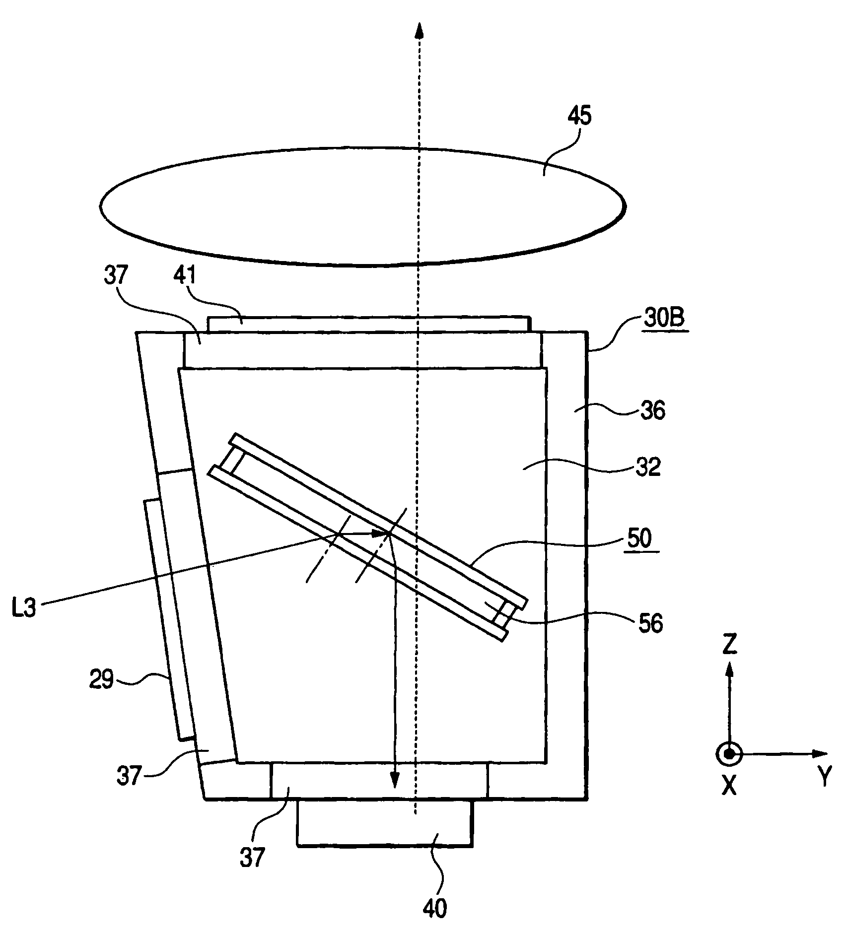
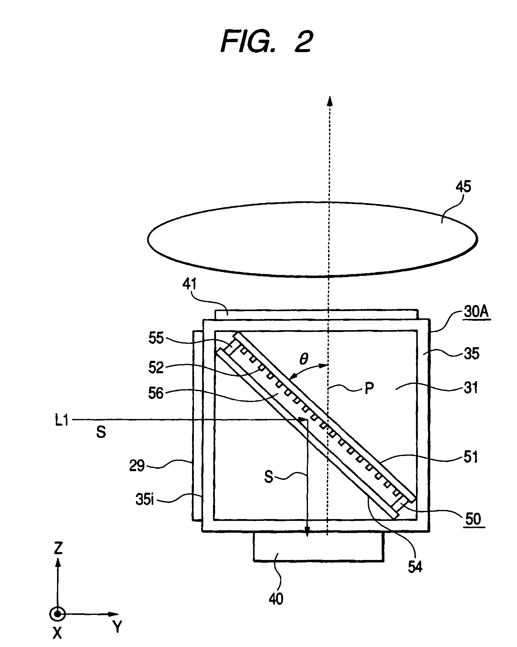
[0042]To prevent a wire grid type polarization split device from deteriorating in the polarization split performance when used in a medium whose refractive index is larger than that of the air, the present invention is characterized in that a thin film layer is placed between the wire grid type polarization split device and the medium. The air layer is designed so thin as not to have astigmatic influence.

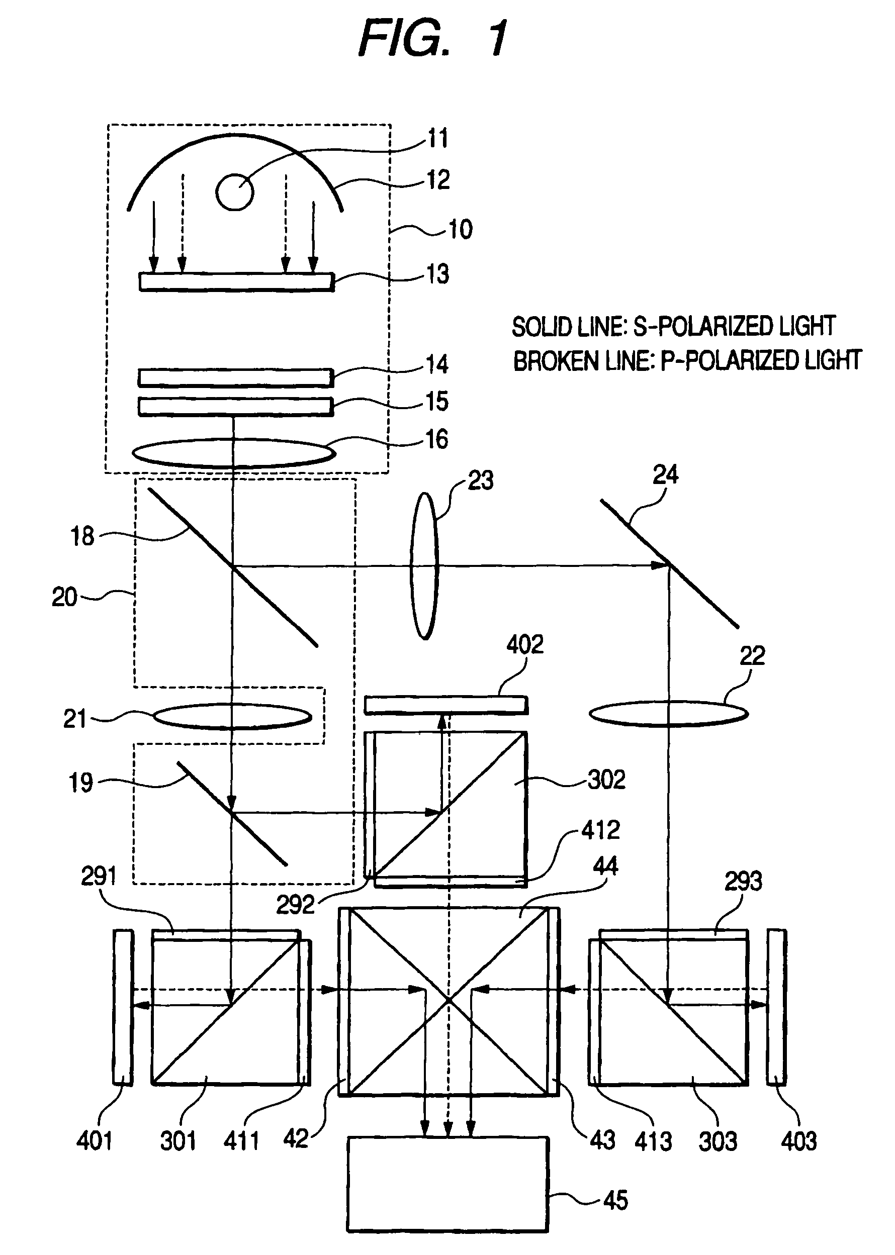
[0043]FIG. 1 shows the configuration of a projection type image display apparatus as an embodiment of the present invention. This is a liquid crystal projector unit where reflective liquid crystal panels are used as light valves.

[0044]In FIG. 1, 11 refers to a light source and 12 refers to a reflector having a parabolic reflective surface. 13 and 14 are a...


PUM


Abstract

A technique according to the present invention allows a projection-type image display system to suppress the temperature rise of the polarization split devices and secure high image quality. Polarization split means has a polarization split device arranged in a medium with a refractive index larger than 1. The polarization split device has a polarization split surface on which a diffractive grating structure is formed to polarize and split light. An air layer is formed in contact with the polarization split surface. In a projection type image display apparatus or an optical unit using this apparatus, light fluxes are polarized and split by the polarization split means before irradiated to light valves and after modulated by the light valves and color composition is made from the polarized and split light fluxes before enlarged and projected by a projection lens unit.

Description

CROSS-REFERENCES TO RELATED APPLICATIONS[0001]The present application is related to and claims priority from Japanese Application Serial No. P2004-059569, filed Mar. 3, 2004, and Japanese Application Serial No. P2004-059553, filed Mar. 3, 2004, the contents of which are hereby incorporated by reference for all purposes.BACKGROUND OF THE INVENTION[0002]The present invention relates to a polarization split technique in a projection-type image display apparatus which forms an optical image according to an image signal by irradiating light valves such as liquid crystal panels with light from the light source side and enlarges / projects the optical image.[0003]Business-use liquid crystal projectors have become widespread. In addition, as a substitute for the conventional projector which displays an image on a cathode-ray tube for projection to a screen, liquid crystal panel-used projection TVs have been developed. In particular, home-use projection TVs require higher fidelity color reprod...

Claims


Application Information

Patent Timeline
Patent Type & Authority Patents(United States)
IPC IPC(8): G03B21/14G02B27/44G02B5/06G02B27/18G02B27/28
CPCG03B21/14G03B21/16G03B21/2073
Inventor NAKASHIMA, TSUTOMUYATSU, MASAHIKOHIRATA, KOJI
Owner MAXELL HLDG LTD
Why Eureka
Try Eureka