Bearing apparatus for a driving wheel of vehicle

a technology for driving wheels and bearings, which is applied in the direction of rigid support of bearing units, couplings, instruments, etc., can solve the problems of reducing the working efficiency, reducing requiring assembly or disassembly, so as to reduce the weight of bearing apparatuses, improve the working efficiency in assembly, and facilitate the disassembly

Inactive Publication Date: 2007-08-14
NTN CORP
View PDF11 Cites 23 Cited by
  • Summary
  • Abstract
  • Description
  • Claims
  • Application Information

AI Technical Summary

Benefits of technology

[0014]According to the present invention, the outer end surface of the wheel hub is formed with an internal thread. The wheel hub and the outer joint member are united by a plate. The plate has a circular aperture formed at a position corresponding to the internal thread. A central aperture is formed with an internal thread. The plate abuts the outer end surface of the wheel hub. A securing bolt is screwed into an internal thread formed in the shaft of the outer joint member through the central aperture of the plate. This structure makes it possible to reduce the weight of the bearing apparatus as well as to easily disassemble the bearing apparatus. This improves the working efficiency in assembling and disassembling the bearing apparatus even though the serration of the stem portion and the wheel hub is fitted in the pre-load condition.
[0015]According to the present invention, the releasing mechanism includes a releasing jig formed with an external thread. An internal thread, which engages the external thread of the releasing jig, is formed on a pilot portion of the wheel hub. Accordingly, it is possible to separate the wheel hub and only mount the releasing jig on the wheel hub by screwing the bolt into the internal thread formed in the center of the releasing jig. Thus, it is possible to improve the working efficiency of assembly and disassembly of the bearing apparatus even though the serration of the stem portion and the wheel hub is fitted in the pre-load condition.
[0016]According to the present invention, the outer end portion of the wheel hub is formed with an annular recess with a tapered internal

Problems solved by technology

However, in such a bearing apparatus for a driving wheel, noise generation or loosening of the nut 113 is sometimes caused during rapid acceleration and deceleration times when circumferential backlash occurs in the fitted portion of the serration 112.
In such a construction, a problem exists in that a machine, such as a press or the like, is required to assemble or disassemble the wheel h

Method used


Image

  • Bearing apparatus for a driving wheel of vehicle
  • Bearing apparatus for a driving wheel of vehicle
  • Bearing apparatus for a driving wheel of vehicle

Examples


first embodiment

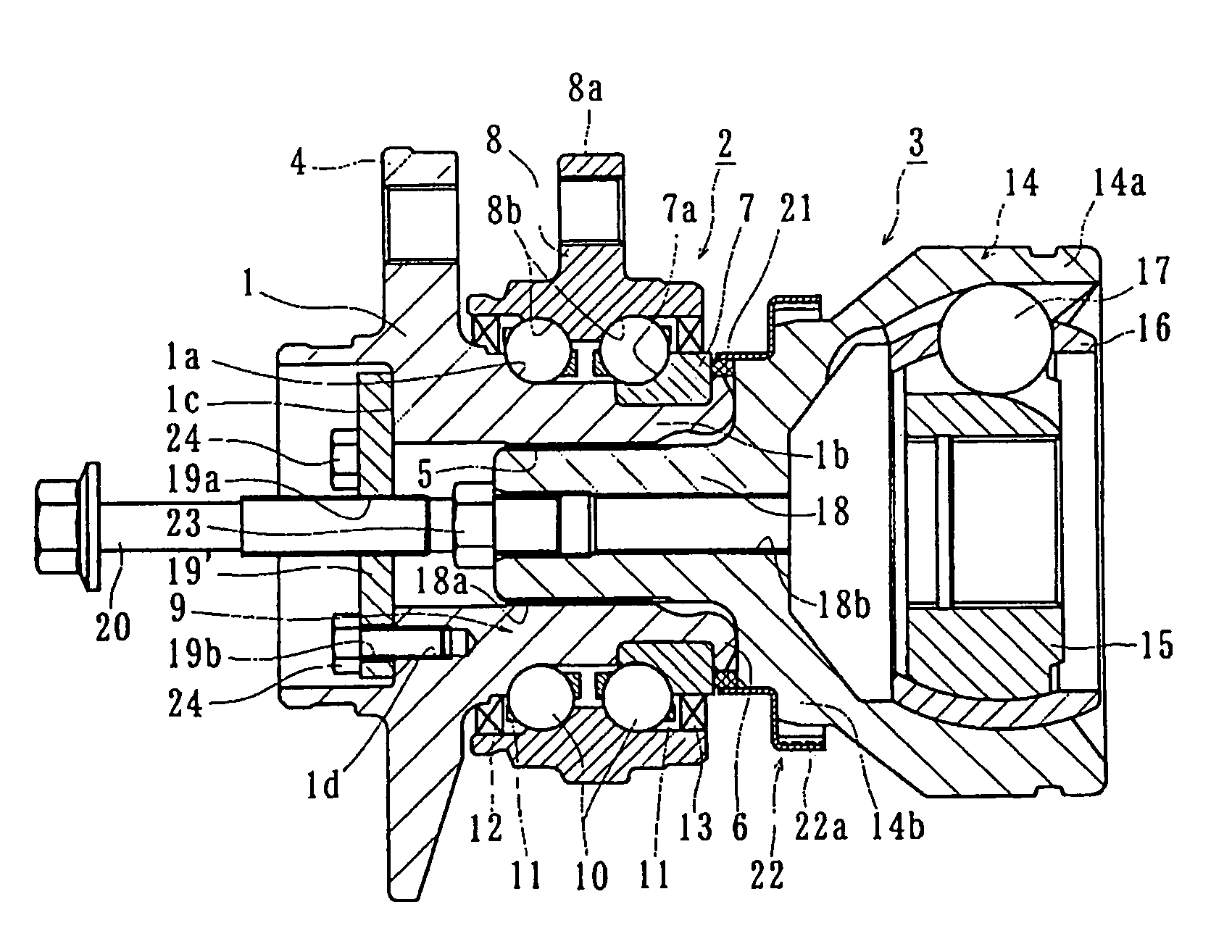
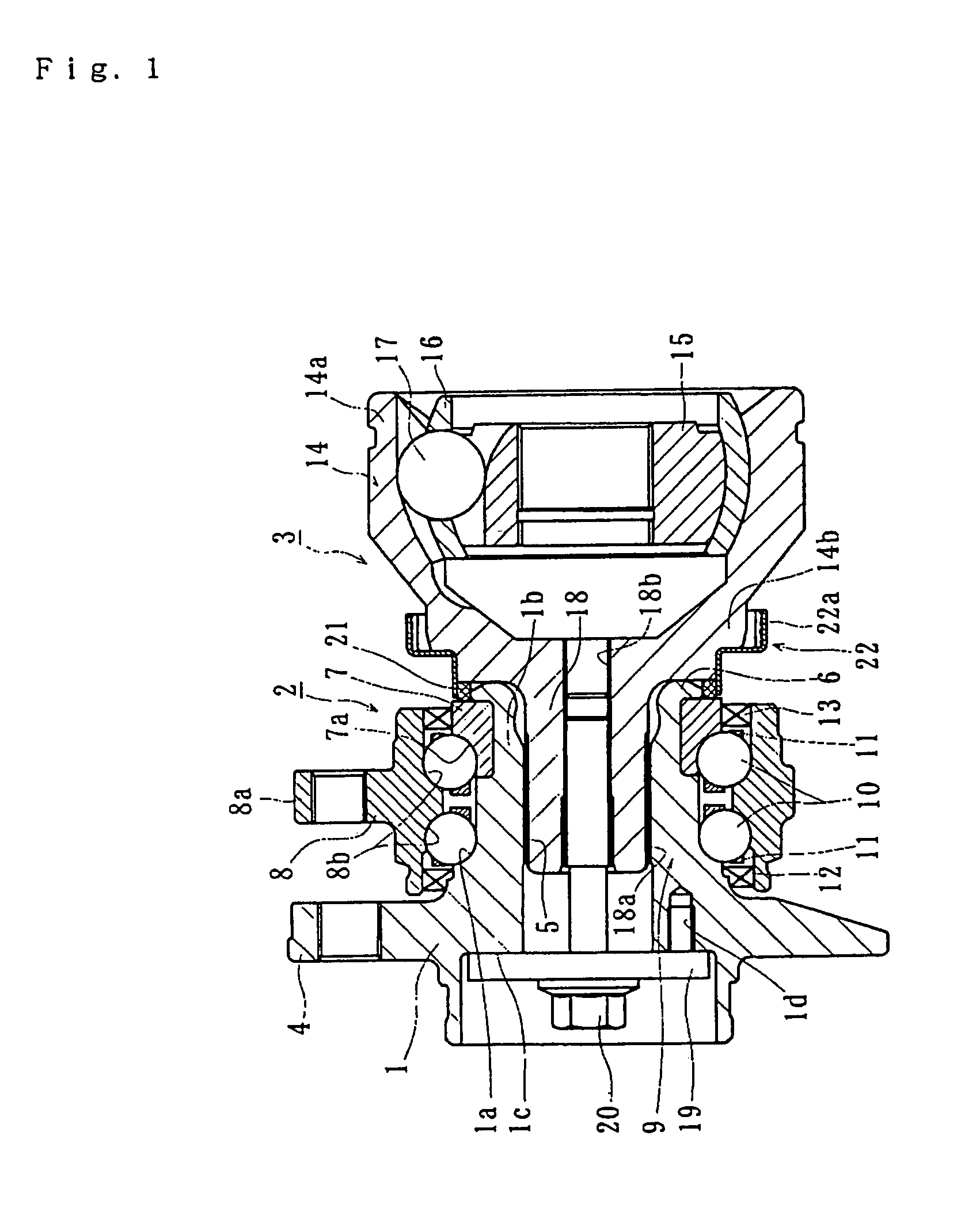
[0034]Preferred embodiments of the present invention will be hereinafter described with reference to the accompanied drawings. FIG. 1 is a longitudinal section view showing a bearing apparatus for a vehicle driving wheel of the present invention.

[0035]The apparatus has a wheel hub 1, a double row rolling bearing 2 and an constant velocity universal joint 3 which are assembled as a unit. In the description below, the term “outboard side” of the apparatus denotes a side which is positioned outside of the vehicle body. The term “inboard side” of the apparatus denotes a side which is positioned inside of the body when the apparatus is mounted on the vehicle body.

[0036]The wheel hub 1 is formed integrally with a wheel mounting flange 4 at the outboard side of the wheel hub 1 on which a wheel (not shown) is mounted. The wheel hub 1 has an inner raceway surface 1a at the outboard side of the double row rolling bearing 2. A cylindrical stepped portion 1b of smaller diameter axially extends ...

second embodiment

[0048]A method for disassembling the bearing apparatus of the second embodiment will be described with reference to FIG. 6. First, the securing nut 27 fastened onto the outer end surface 1c of the wheel hub 1′ is removed. The caulked portion 27a of the securing nut 27 is deformed. A releasing jig 28 is inserted within a pilot portion le of the wheel hub 1′. The inner circumferential surface is formed with an internal thread 29 and the outer circumferential surface of the releasing jig 28 is formed with an external thread 28a to engage with the internal thread 29. FIG. 7(a) is a front elevation view of the releasing jig 28. FIG. 7(b) is a cross section view. The releasing jig 28 has a generally cup-shaped configuration and is formed with a flat chamfered surface 28b on its bottom and a internal thread 28c at its center.

[0049]The bolt 30 is screwed into the internal thread 28c of the releasing jig 28. The tip end of the bolt 30 abuts the stem portion 26. Thus, the outer joint member 2...


PUM

PropertyMeasurementUnit
Angleaaaaaaaaaa

Abstract

A bearing apparatus for a vehicle driving wheel has a pre-loading mechanism formed in the serration fitted portion between the stem portion of the outer joint member and the wheel hub. A fastening member combines the wheel hub and the outer joint member. A releasing member, adapted to be arranged on the wheel hub, enables removal of the fastening mechanism.

Description

CROSS-REFERENCE TO RELATED APPLICATIONS[0001]This application claims priority to Japanese Patent Application No. 2002-227447 filed Aug. 5, 2002, which application is herein expressly incorporated by reference.FIELD OF THE INVENTION[0002]The present invention relates to a bearing apparatus for rotatably supporting a driving wheel of a vehicle.BACKGROUND OF THE INVENTION[0003]A power transmission apparatus transmits power from the vehicle engine to the vehicle wheels. The apparatus enables radial, axial and moment displacements caused by the bound of wheels and the turning of the vehicle during travel. The apparatus includes a drive shaft 100 arranged between the engine and the driving wheel. One end of the drive shaft 100 is connected to a differential gear 102 via a slidable constant velocity universal joint 101. The other end of the drive shaft is connected to a wheel 105 via a bearing apparatus 104 which includes a fixed type constant velocity universal joint 103, as shown in FIG....

Claims


Application Information

Patent Timeline
IPC IPC(8): F16C13/00F16D3/20B60B27/00F16D1/06G01P3/44
CPCB60B27/00B60B27/0005B60B27/0026B60B27/0042B60B27/0094G01P3/443B60B27/0084Y10T29/53848Y10T29/53883F16C19/186F16C35/062F16C35/0635F16C2326/02
Inventor YAMAMOTO, KEN
Owner NTN CORP
Why Eureka
Try Eureka