
Engine block component brace

a technology for engine blocks and components, applied in the direction of machines/engines, casings, cylinders, etc., can solve the problems of engine block or block failure, many components of reciprocating motors, and many components subject to high operational loads during operation, so as to reduce the distortion of the engine block

Active Publication Date: 2007-08-21
PELMEAR DOUGLAS A
View PDF5 Cites 16 Cited by
  • Summary
  • Abstract
  • Description
  • Claims
  • Application Information

AI Technical Summary

Benefits of technology

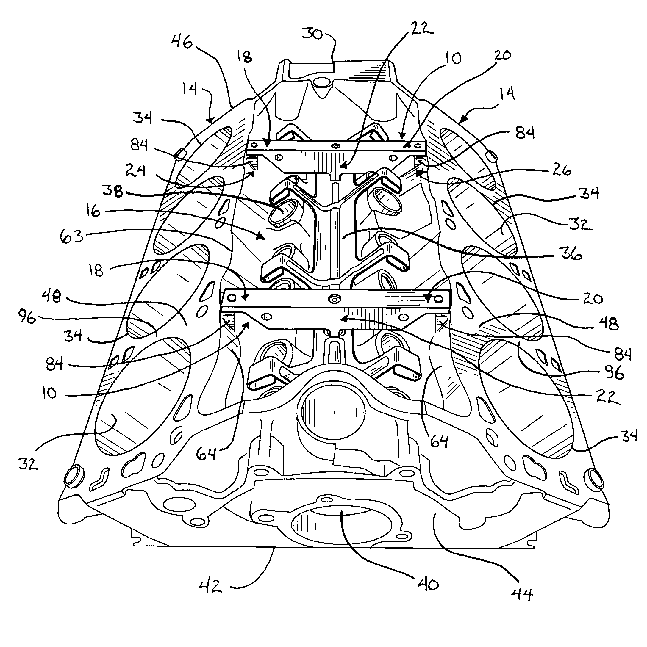
[0011]The present invention provides a component brace for attachment within the upper valley of a V-styled engine block, where one or more of the component braces may be mounted within and substantially span the upper valley of the engine block between the cylinder banks to reduce distortion of the engine block.
[0014]The mounting of one or more component braces in the upper valley of V-styled engine blocks provides strength to the engine block to resist deformation of the engine block when used in an operating motor. The component braces include first and second mounting portions separated by a body portion, where the mounting portions may be constructed as arms extending from the body portion. An intermediate mounting portion may also be included that is centrally located with respect to the first and second mounting portions, but below a line defined by the first and second mounting portions. The component brace thus forms an approximately inverted triangular or truss like configuration having three points of contact with three mounting areas on the engine block, with the mounting areas being located proximate the left and right cylinder banks and at the base of the upper valley. The securing of the component brace at the mounting areas provides rigidity to the upper portion of the engine block to resist deformation, such as would occur as relative movement between the cylinder banks. The resistance to such deformation aids in the prevention of cylinder bore wall distortion as well as engine block cracking. A motor constructed using an engine block having one or more component braces mounted thereto will utilize less fuel and may operate under higher loads with a reduced risk of failure.

Problems solved by technology

Many of the components of reciprocating motors, such as automobile, light truck, and heavy-duty motors, are subjected to high loads during operation.
One such component subjected to high operational loads is the engine block or block, which experience loads from the combustion events occurring in the combustion chambers formed by the cylinder heads, pistons, and cylinder bores of the block.
These forces impart strain on the engine block, which results in distortion and can even lead to failure of the engine block.
The cylinder bores are one such area subject to distortional strains, with this area experiencing significant distortion due to their proximity to the origin of the forces and the relatively narrow walls of the cylinder bores.
Distortion to the cylinder bores can be very problematic to the operation of reciprocating motors.
Furthermore, upon a combustion event, the burnt gasses can escape past the piston rings and reduce the force transmitted to the crankshaft, thus further reducing the power output of the motor.
In addition, such distortion can improperly allow the discharging of combustion exhaust gasses into the oil pan area, and allow oil to enter the combustion chamber and increase harmful emissions.
Distortion to the engine block cylinder bores, therefore, reduces the efficiency of a reciprocating motor as measured by the amount of fuel consumed relative to the power output, thus necessitating that the motor utilize more fuel to obtain a desired power output than would otherwise be required, and can increase harmful emissions.
Distortion to the engine block can also result in total failure of the motor due to cracking of the block or can cause the piston to seize in the cylinder bore due to an excessively out of round condition of the bore.
Engine blocks are most commonly constructed of cast iron, but may alternatively be constructed from aluminum, or other alloys or materials, and are relatively inelastic.
Therefore, strain causing distortion can cause cracks to form in engine blocks, particularly at sharp corners or areas having thinner wall sections or at voids formed during the casting operation.
The cyclic nature of the strain can cause the cracks to propagate and cause the motor to fail.
Distortion of engine blocks is a problem for all motors, whether spark ignition (SI) gasoline motors or combustion ignition (CI) diesel motors or alternative fuel burning motors.
However, engine blocks formed to have a V-style configuration are particularly apt to experience distortion causing strain.
The non-linear forces resulting from the offset relationship of the pistons firing within the angled cylinder banks and the extension of the cylinder banks from the central portion of the engine block contribute to the strain causing distortion in this area of an engine block.
However, the disclosed reinforcement plate does not provide reinforcement to the upper portion of the engine block adjacent the cylinder bores.

Method used


Image

  • Engine block component brace
  • Engine block component brace
  • Engine block component brace

Examples


Embodiment Construction

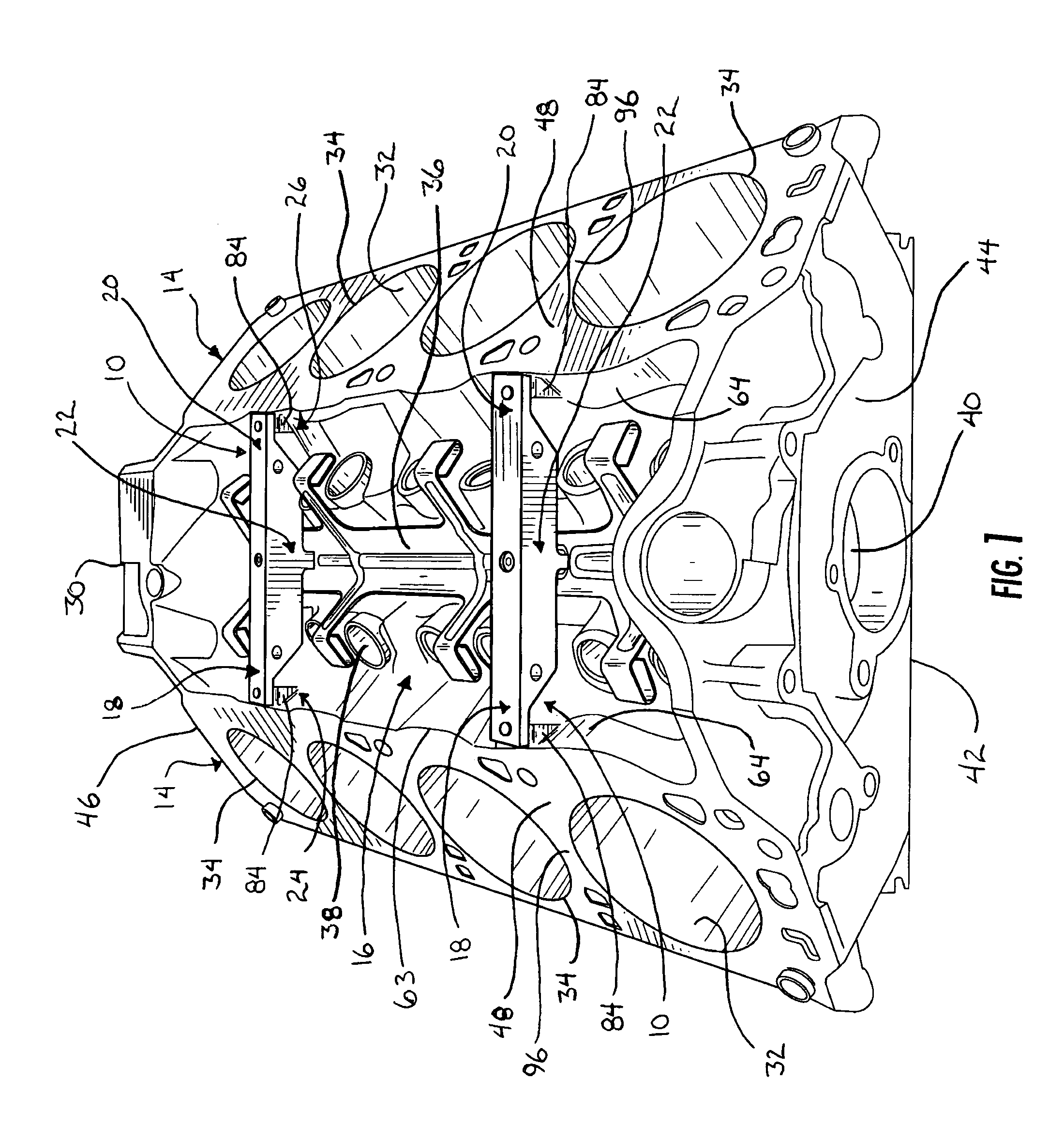
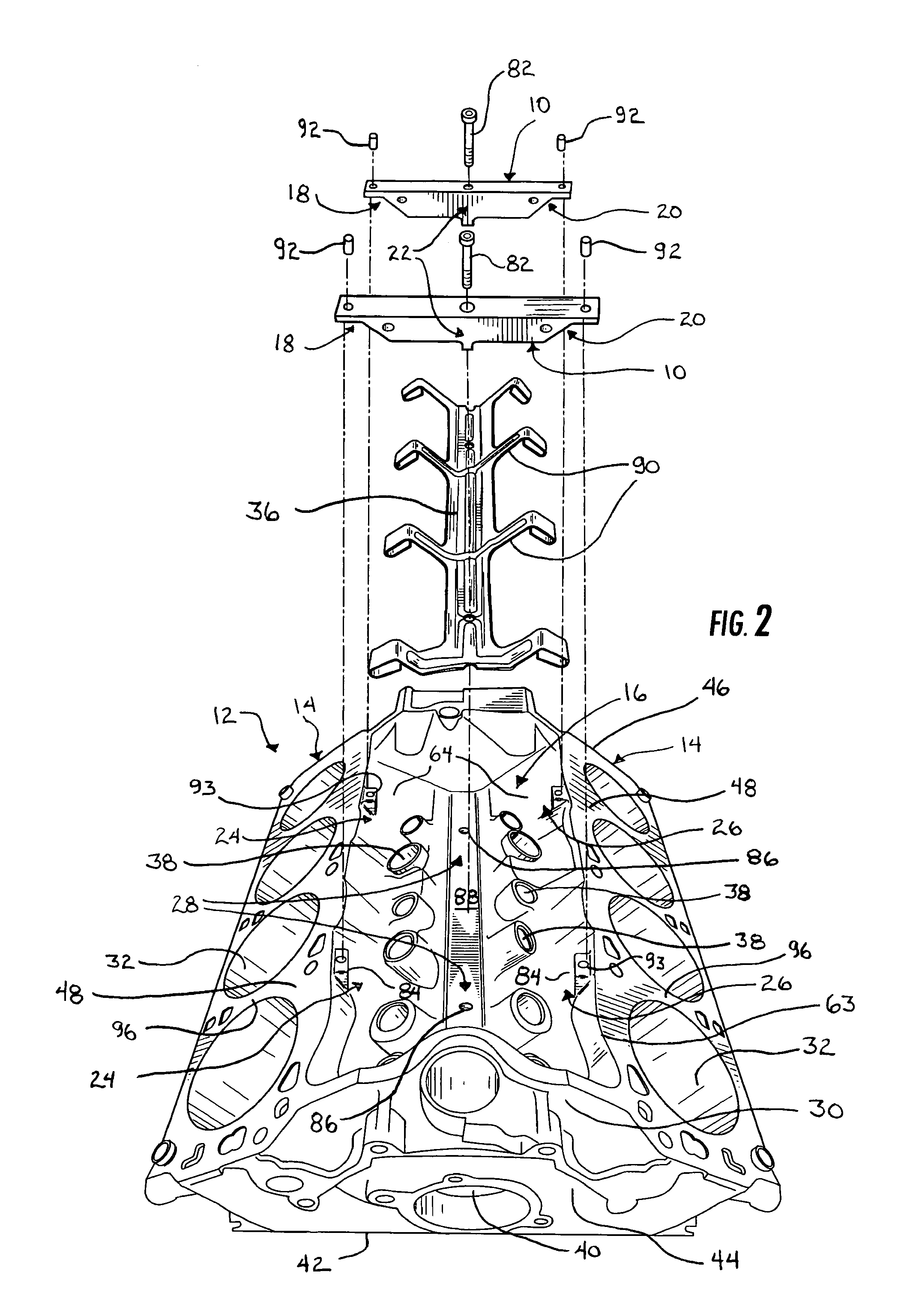
[0027]The present invention will now be described with reference to the accompanying figures, wherein the numbered elements in the following written description correspond to like-numbered elements in the figures. Two component braces or truss devices or ribs 10 are shown in FIG. 1 mounted to a “V” styled engine block 12, where the V configuration is formed by the angled orientation of the two cylinder banks 14 of engine block 12 with respect to one another. The component braces 10 are positioned in and substantially span the upper valley or lifter valley 16 of the engine block 12 to provide strength to engine block 12 and resist deformation of the engine block 12 when used in an operating motor.

[0028]As generally illustrated in FIGS. 1 and 2 and described in more detail below, each component brace 10 includes first and second mounting portions or members 18, 20 and an intermediate mounting portion or member 22. The mounting portions 18, 20, 22 contact the engine block 12 at three p...


PUM


Abstract

One or more component braces may be installed into the upper valley of a V-styled engine block to provide resistance to deformation of the block when used in an operating motor. The component braces include first and second mounting portions separated by a body portion, where the mounting portions may be constructed as arms extending from the body portion. An intermediate mounting portion may also be included that is centrally located with respect to the first and second mounting portions, but below a line defined by the first and second mounting portions. The securing of the component brace at the mounting areas provides rigidity to the upper portion of the engine block to resist deformation, such as would occur as relative movement between the cylinder banks. The resistance to such deformation aids in the prevention of cylinder bore wall distortion as well as engine block cracking.

Description

BACKGROUND OF THE INVENTION[0001]The present invention is directed to preventing deformation of an engine block of a motor, and in particular to a brace for mounting to an engine block to prevent deformation.[0002]Many of the components of reciprocating motors, such as automobile, light truck, and heavy-duty motors, are subjected to high loads during operation. One such component subjected to high operational loads is the engine block or block, which experience loads from the combustion events occurring in the combustion chambers formed by the cylinder heads, pistons, and cylinder bores of the block. These forces are transmitted to the engine block at, amongst other locations, the cylinder heads and the crankshaft, which is mounted to the engine block.[0003]A portion of the forces that are applied to the engine block are imparted in a non-linear dynamic manner due to the alternating firing sequence of the pistons and the reciprocating connection of the connecting rods to the pistons...

Claims


Application Information

Patent Timeline
IPC IPC(8): F02F7/00F02B75/22
CPCF02F7/0012
Inventor PELMEAR, DOUGLAS A
Owner PELMEAR DOUGLAS A
Learn More