
Coil element selection method and magnetic resonance imaging apparatus

a selection method and coil element technology, applied in the field of coil element selection method and magnetic resonance imaging apparatus, can solve the problems of increasing the workload of imaging technicians and physicians, difficulty in selecting the optimum coil element, and difficulty in most optimum coil element selection, etc., to reduce the retaking of mri shoots, shorten the time, and be easy to understand

Inactive Publication Date: 2007-08-21
GE MEDICAL SYST GLOBAL TECH CO LLC
View PDF20 Cites 16 Cited by
  • Summary
  • Abstract
  • Description
  • Claims
  • Application Information

AI Technical Summary

Benefits of technology

[0014]Therefore, the present invention has an object to provide a method of coil element selection of a magnetic resonance imaging apparatus, which allows selecting in an easier and positive manner the coil element and a combination of coil elements most suitable to the MRI imaging by the imaging technician operating the MRI apparatus.
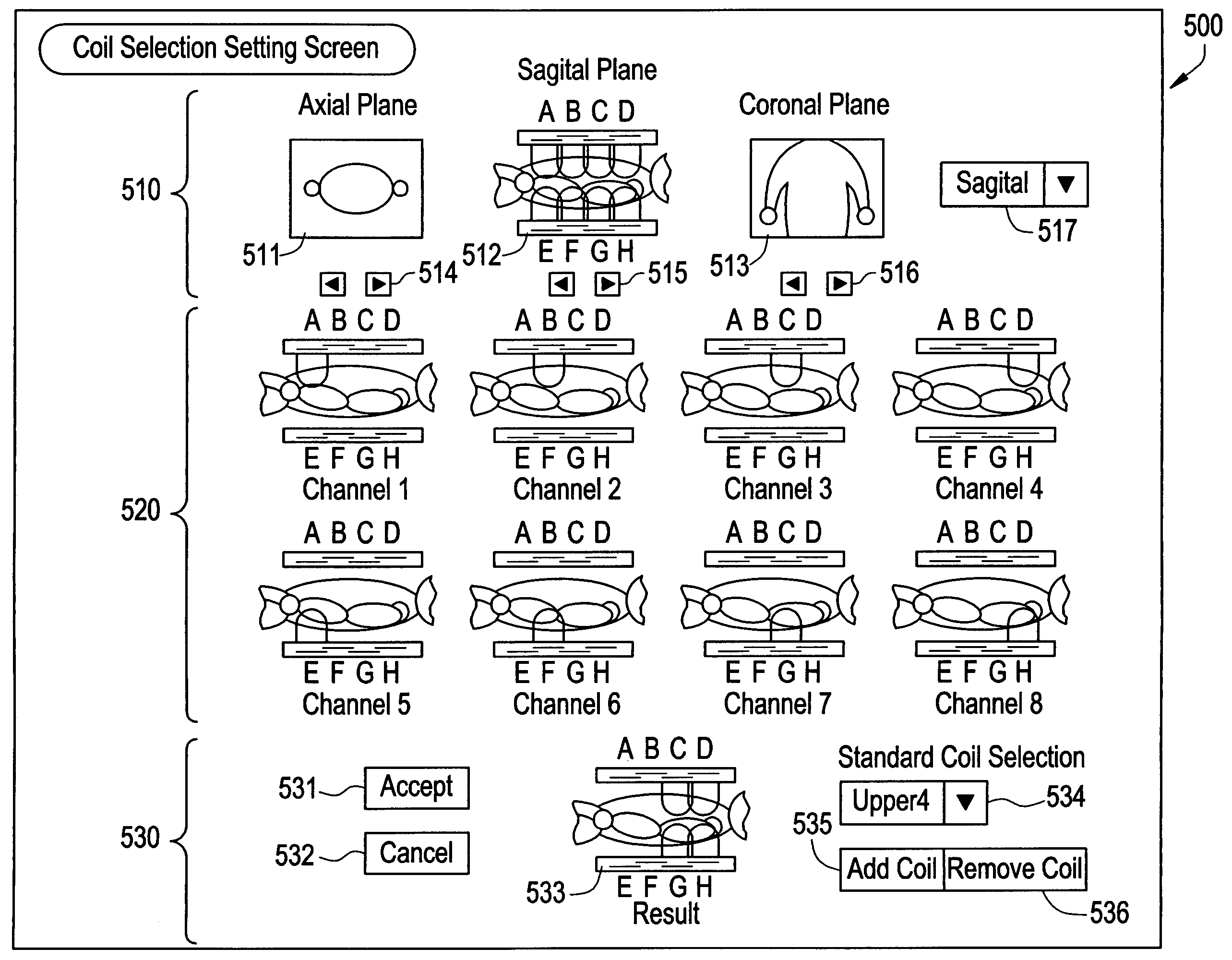
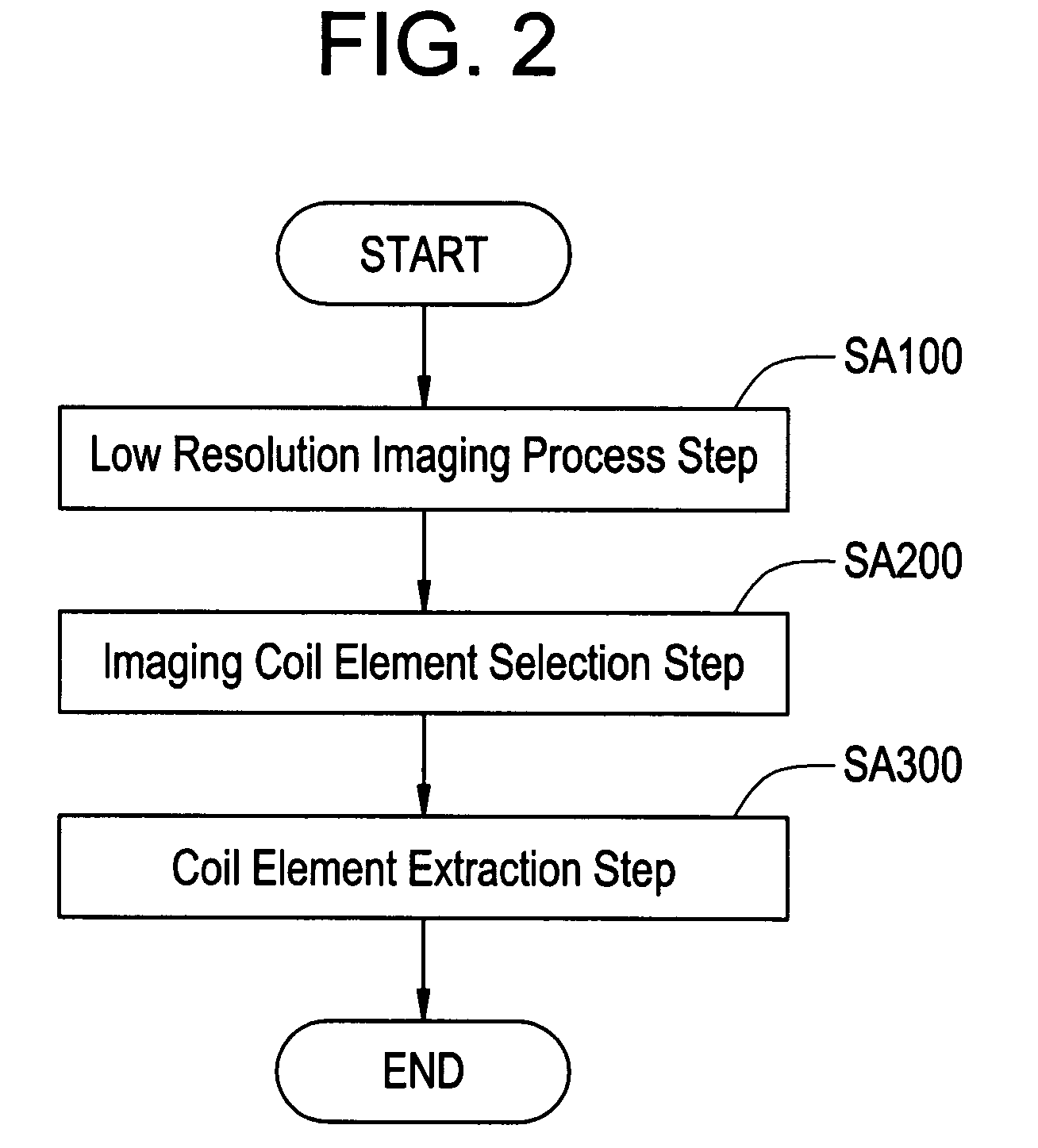
[0031]In accordance with the present invention, the coil element selection step includes a function of selecting the optimum coil element which is the most suitable for the imaging sensitivity with respect to the imaging site of a subject by any coil element of a plurality of coil elements constituting the phased array coil; the coil element selection step includes the low resolution imaging step for imaging at low resolution by means of a plurality of coil elements, the imaging channel selection step for selecting the imaging channel which is the most suitable for the imaging site from within a plurality of low resolution images taken by the low resolution imaging step, and the coil element extraction step for extracting the coil element selected by the imaging channel selection step, so that the position of imaging site can be visually recognized in an efficient and positive manner in a shorter time, as well as the coil element which is candidate of imaging at a higher sensitivity the imaging site can be determined from within a plurality of coil elements.
[0032]By providing a coil element selection method that is intuitive and easy to understand for the imaging technician, the present invention has the effect that the operator may readily select a coil element appropriate for the purpose while at the same time decreasing the retaking of MRI shoots, and that improves the efficiency of MRI diagnosis.
[0033]The coil element selection method and magnetic resonance imaging apparatus in accordance with the present invention is obviously useful for MRI apparatus, more specifically for, among others, the coil element selection method in which the technician is allowed readily and positively selecting either a coil element and a combination of coil elements, most suitable for the MRI imaging.

Problems solved by technology

The MRI apparatus of the prior art as have been described above, however, may have the problems as cited below.
This poses a problem of difficulty of selecting the optimum coil element most suitable for the practical MRI measurement.
In order to adjust the sensitivity direction of coil element therefore a work is needed for changing the coil element disposition, leading to a problem that the burden of the amount of work of the imaging technician and physician increases, as well as to another troublesome problem that after having an MRI imaging session, the MRI imaging should be run again if the mounting position of phased array coil is not appropriate.

Method used


Image

  • Coil element selection method and magnetic resonance imaging apparatus
  • Coil element selection method and magnetic resonance imaging apparatus
  • Coil element selection method and magnetic resonance imaging apparatus

Examples


Embodiment Construction

[0042]By referring to accompanying drawings, some preferred embodiments of the coil element selection method and the magnetic resonance imaging apparatus in accordance with the present invention will be described in greater details herein below. In the following description, the overview and feature of the system configuration for carrying out the coil element selection method and the magnetic resonance imaging apparatus in accordance with first preferred embodiment will be described first, then the processes of coil element selection method will be described in greater details thereafter.

PREFERRED EMBODIMENTS

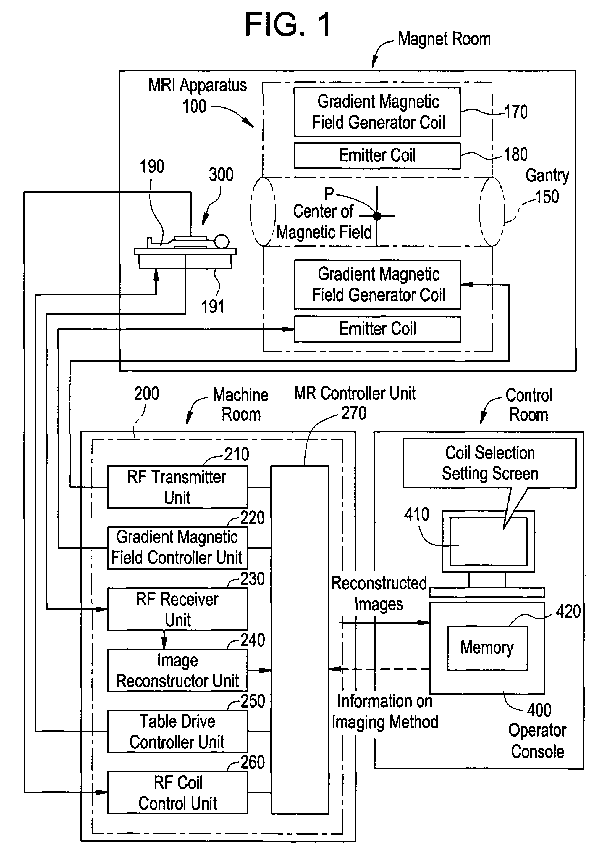
[0043]FIG. 1 shows a functional schematic block diagram indicative of an exemplary system configuration for carrying out the coil element selection method in accordance with the present invention. The feature of the coil element selection method of the present invention is such that low resolution images of the subject will be taken in advance to thereby use those low resoluti...


PUM


Abstract

To visually, readily and positively performing the selection of a coil element and a combination of coil elements most suitable for the MRI scan, a low resolution imaging step for imaging at a low resolution by using a plurality of coil elements A to H, an imaging coil element selection step for selecting the optimum coil element for imaging site from the low resolution images taken in the low resolution imaging step, and a coil element extraction step for extracting coil element selected in the imaging coil element selection step are comprised such that a low resolution image of the subject is preliminarily taken to use thereby to visually select the coil element.

Description

CROSS REFERENCE TO RELATED APPLICATIONS[0001]This application claims the benefit of Japanese Application No. 2004-371941 filed Dec. 22, 2004.BACKGROUND OF THE INVENTION[0002]The present invention relates to an emission coil for emitting electromagnetic waves of a predetermined frequency to an RF coil mounted on a subject being carried in a static magnetic field and an MRI apparatus for imaging a magnetic resonance image by receiving a magnetic resonance signal emitted from the subject, and more specifically to a method of coil element selection of a magnetic resonance imaging apparatus which allows selecting the optimum coil element suitable for MR measurement from within a plurality of coils embedded in a phased array coil, in accordance with the lesion to be imaged.[0003]There has been known a magnetic resonance imaging apparatus (MRI apparatus herein below) for imaging the internal structure of a subject to be imaged by means of magnetic resonance phenomenon hitherto. Since the m...

Claims


Application Information

Patent Timeline
Patent Type & Authority Patents(United States)
IPC IPC(8): G01V3/00
CPCG01R33/3415G01R33/3664G01R33/546A61B5/055
Inventor NABETANI, AKIRANOZAKI, ATSUSHI
Owner GE MEDICAL SYST GLOBAL TECH CO LLC
Learn More