Reflecting board with variable slot size for a microstrip reflectarray antenna

a microstrip reflectarray and slot size technology, which is applied in the direction of antennas, antenna details, antenna earthings, etc., can solve the problems of ineffective high-frequency signal reflected by the disc, difficult disc design, and easy to affect the entire performance of the reflecting array antenna, so as to improve the sensitivity of the microstrip reflectarray antenna performance, reduce the manufacturing precision of the reflecting board, and improve the design flexibility of the reflecting board

Inactive Publication Date: 2007-08-21
TATUNG UNIVERSITY +1
View PDF5 Cites 7 Cited by
  • Summary
  • Abstract
  • Description
  • Claims
  • Application Information

AI Technical Summary

Benefits of technology

[0012]Therefore, through forming a slot in the second microstrip antenna patch, the design flexibility of the reflecting board is improved, and the sensitivity of the performance of the microstrip reflectarray antenna to the manufacturing precision of the reflecting board is reduced. Moreover, the same performance of the reflecting board can be obtained by using a microwave substrate with high dielectric constant. Comparing with the conventional microstrip reflectarray antenna, the cost of the reflecting board of the present invention is lessened, the area of the reflecting board of the present invention is reduced, and the yield of the reflecting board of the present invention is enhanced.

Problems solved by technology

However, the entire performance of reflecting array antenna is easily affected by the size and arrangement of the patterns of the antenna patches due to the material properties of the disc (e.g. the dielectric constant).
Hence, producing the design of the disc is very difficult.
Besides, the size and the position of every antenna patch needs to be manufactured precisely, otherwise, the high-frequency signal cannot be reflected effectively by the disc, and the performance (e.g. gain, bandwidth, or efficiency) of the disc can not be improved.

Method used


Image

  • Reflecting board with variable slot size for a microstrip reflectarray antenna
  • Reflecting board with variable slot size for a microstrip reflectarray antenna
  • Reflecting board with variable slot size for a microstrip reflectarray antenna

Examples


Embodiment Construction

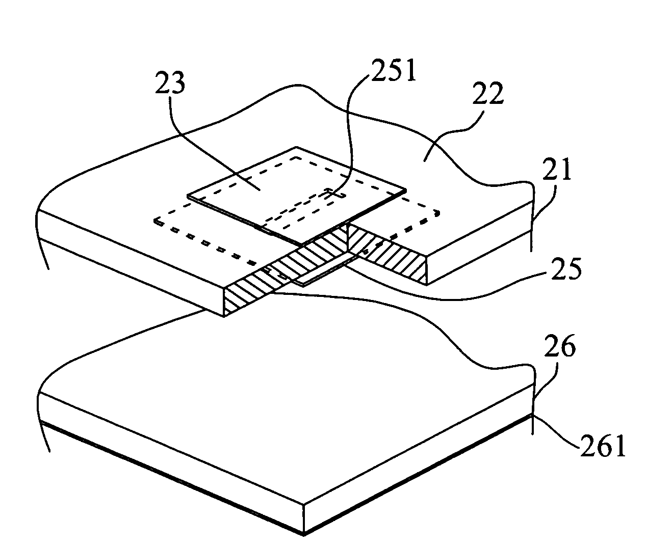
[0032]FIG. 2A and FIG. 2B illustrate the top view and bottom view of the reflecting board of the first preferred embodiment of the present invention, respectively. FIG. 2A shows that plural first microstrip antenna patches 23 are disposed on the upper surface 22 of the top substrate 21. Each first microstrip antenna patch 23 is a square in shape, and its area depends on its location on the upper surface 22 of the top substrate 21. FIG. 2B shows that plural second microstrip antenna patches 25 with rectangular slots 251 are disposed on the lower surface 24 of the top substrate 21. Each second microstrip antenna patch 25 is a square in shape, and its area depends on its location on the top substrate.

[0033]Referring to FIGS. 2A and 2B, the second microstrip antenna patch 25, which is opposite to the first microstrip antenna patch 23, corresponds to the first microstrip antenna patch 23 one-to-one. Therefore, each first microstrip antenna patch 23 and its corresponding second microstrip...


PUM


Abstract

The present invention relates to a reflecting board for a microstrip reflectarray antenna and, more particularly, to a reflecting board with variable slot size that can improve the design flexibilities of the reflecting board and reduce the sensitivity to the manufacturing tolerances of the microstrip reflectarray antenna. The reflecting board comprises a bottom substrate having a first lower surface, and a top substrate. Plural first microstrip antenna patches, and plural second microstrip antenna patches with rectangular slots are disposed on the upper surface and the second lower surface of the top substrate, respectively. The area of the second microstrip antenna patches is larger than that of the first microstrip antenna patches. Besides, the ratio of the maximum border-length of the rectangular slot to the maximum border-length of the corresponding second microstrip antenna patch is identical for each second microstrip antenna on the second lower surface of the top substrate.

Description

BACKGROUND OF THE INVENTION[0001]1. Field of the Invention[0002]The present invention relates to a reflecting board for a microstrip reflectarray antenna and, more particularly, to a reflecting board with variable slot size that can improve the design flexibilities of the reflecting board and reduce the sensitivity to the manufacturing tolerances of the microstrip reflectarray antenna.[0003]2. Description of Related Art[0004]To provide broad bandwidth for high frequency communication, a microstrip reflectarray antenna is often used to transmit and receive a high frequency signal. As shown in FIG. 1A, the microstrip reflectarray antenna comprises a disc 11 and a horn 12. In addition, plurality of antenna patches 14 are disposed on the upper surface 13 of the disc 11, and a metal grounding-layer (not shown) is disposed on the lower surface of the disc 11. The horn 12 is coupled to the disc 11 through a support 15 at a predetermined distance above the disc 11. Therefore, as the reflect...

Claims


Application Information

Patent Timeline
Patent Type & Authority Patents(United States)
IPC IPC(8): H01Q1/38
CPCH01Q15/0006H01Q15/0013
Inventor CHANG, THE-NANCHEN, BOR-TSONG
Owner TATUNG UNIVERSITY
Why Eureka
Try Eureka