
Fluid analysis apparatus

a technology of fluid analysis apparatus and assembly, which is applied in the direction of sampling, instruments, measurement devices, etc., can solve the problems of limited success in installing radiant energy guiding elements into flow cells, multi-unit flow cell assemblies that are difficult to be hydraulically sealed to one another, and stainless steel manufacturing methods that are difficult to achieve. , to achieve the effect of enhancing the reliability of mounting accuracy, enhancing the accuracy and repeatability of fluid analysis cell construction, and simplifying construction

Inactive Publication Date: 2007-08-21
WATERS TECH CORP
View PDF48 Cites 15 Cited by
  • Summary
  • Abstract
  • Description
  • Claims
  • Application Information

AI Technical Summary

Benefits of technology

[0012]By means of the present invention, an improved fluid sample analysis apparatus is provided for simplifying construction and enhancing the reliability of mounting accuracy of radiant energy guiding members therewithin. Such enhanced accuracy and repeatability of fluid analysis cell construction correspondingly enhances the accuracy achievable in spectrophotometry of fluid samples being analyzed within such cells.
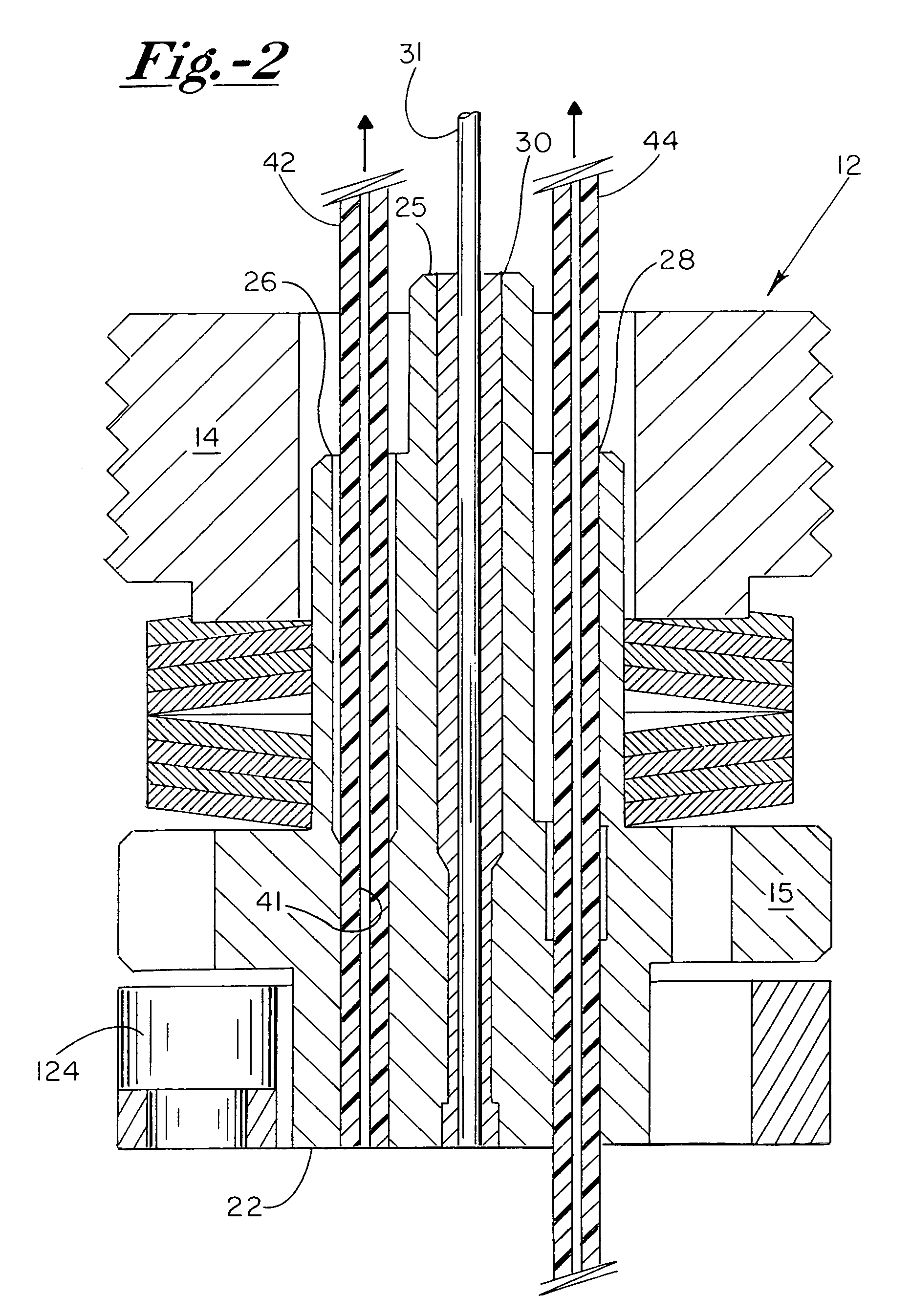
[0013]In a particular embodiment, a method for installing a radiant energy transmitting member in a fluid analysis apparatus includes first providing a cell body assembly having an open bore extending at least partially therethrough, with the open bore having first and second opposing open ends. A compressible hollow ferrule is further provided having an inside diameter substantially equal to an outer diameter of the radiant energy transmitting member, and an unstressed outside diameter that is slightly larger than a first diameter dimension of the open bore. The method further includes mounting the ferrule about a first end of the radiant energy transmitting member and inserting a second end of the radiant energy transmitting member into the first end of the open bore to an extent wherein the ferrule is engaged therewithin. The insertion of the ferrule operably causes the ferrule to compress radially inwardly about the radiant energy transmitting member, thereby frictionally engaging and securing the radiant energy transmitting member within the open bore.

Problems solved by technology

While various such fluid sample analysis cells and assemblies are currently utilized in the field, certain operational and implementational deficiencies exist.
For example, multi-unit flow cell assemblies have found difficulty in being hydraulically sealed to one another when relatively rigid materials such as stainless steel are desired in the fabrication of the bulk cell body parts.
In addition, methods for installing radiant energy guiding elements into such flow cells, and particularly those manufactured from stainless steel, have been met with limited success, or are relatively inefficient and expensive to implement.

Method used


Image

  • Fluid analysis apparatus
  • Fluid analysis apparatus
  • Fluid analysis apparatus

Examples


Embodiment Construction

[0027]The objects and advantages enumerated above together with other objects, features, and advances represented by the present invention will now be presented in terms of detailed embodiments described with reference to the attached drawing figures which are intended to be representative of various possible configurations of the invention. Other embodiments and aspects of the invention are recognized as being within the grasp of those having ordinary skill in the art.

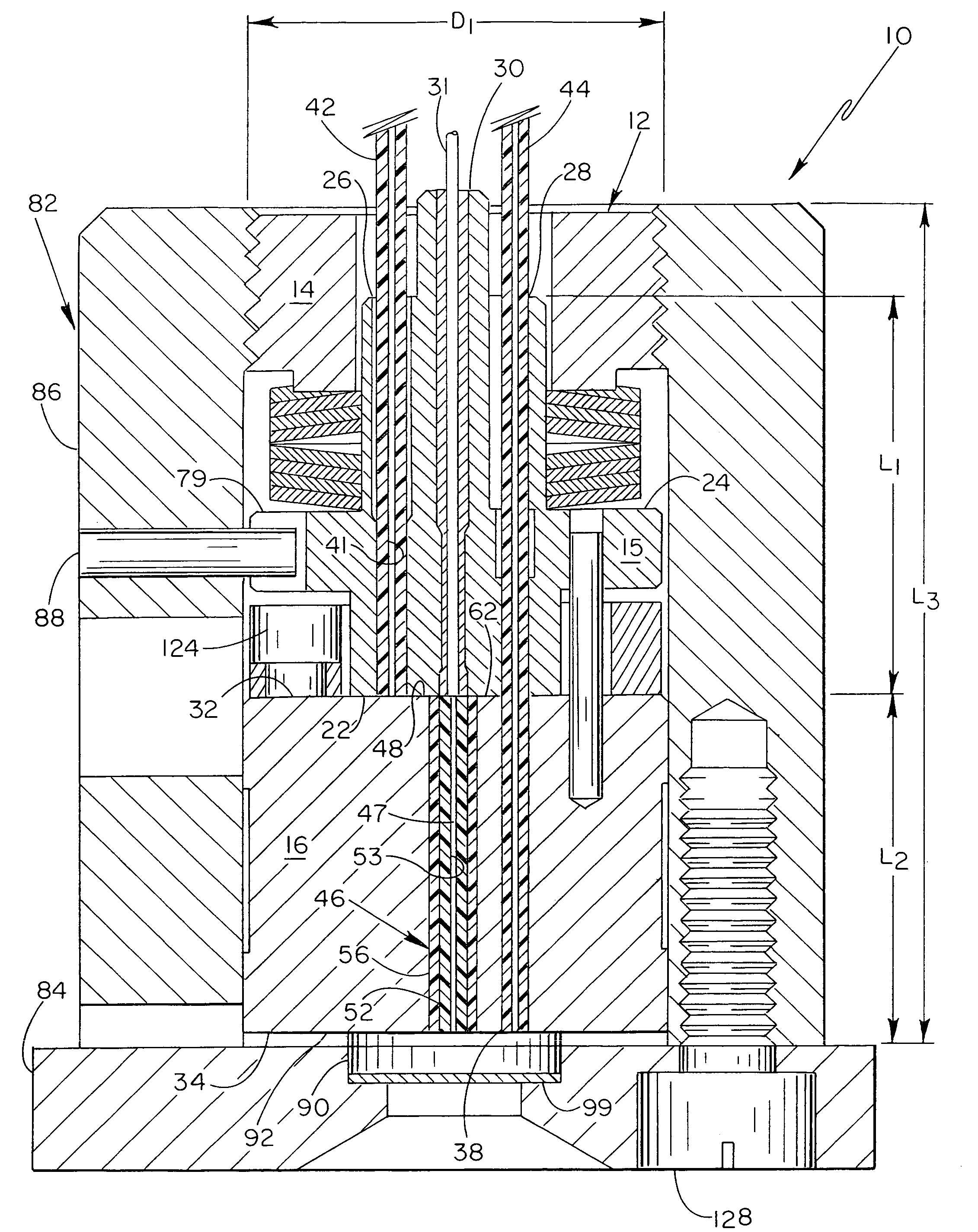
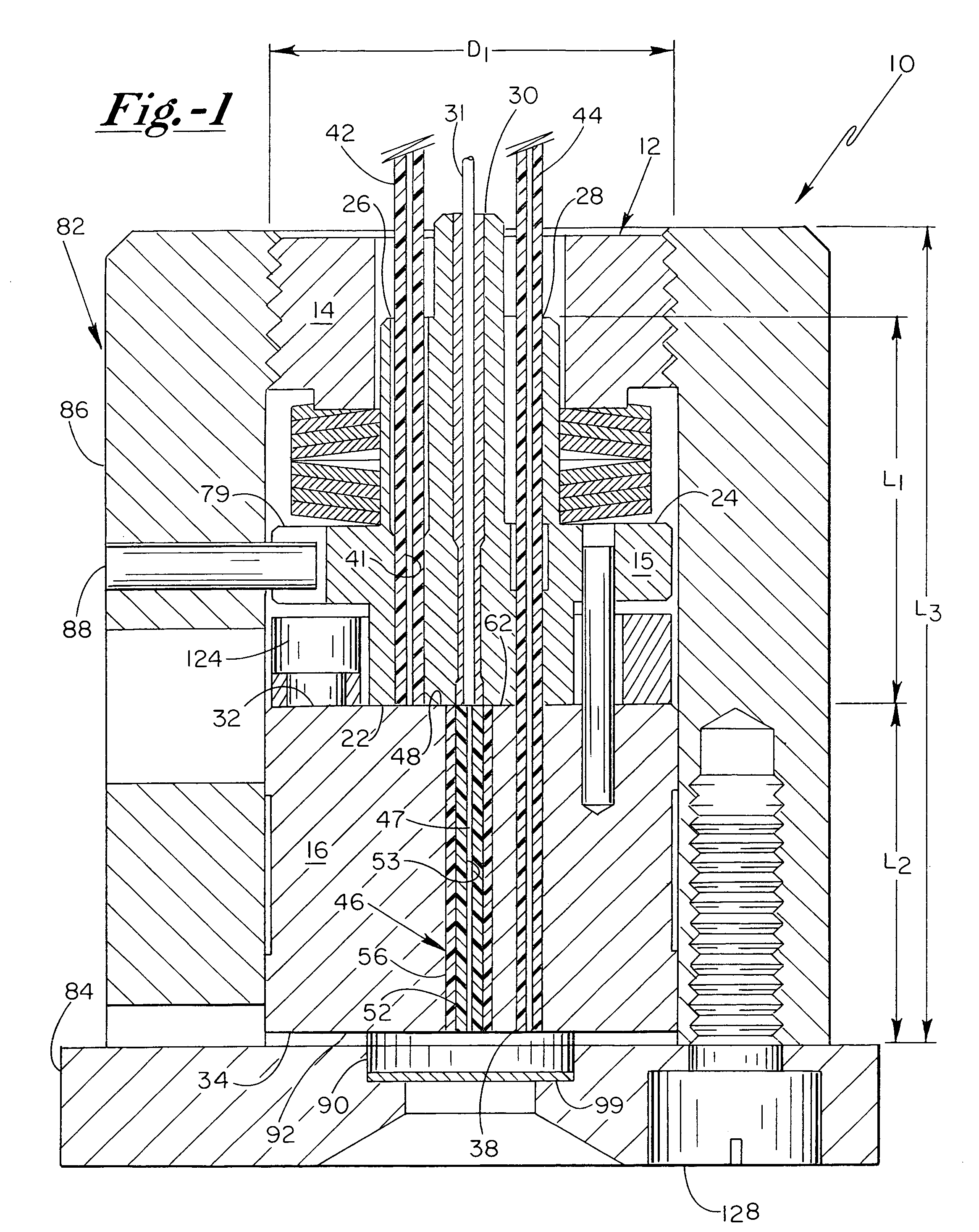
[0028]With reference now to the drawing figures, and first to FIG. 1, a fluid analysis apparatus 10 of the present invention is shown in cross-section, and includes a cell body assembly 12 having first and second portions 15, 16 which are operably disposed in fluid and optical communication with one another. As illustrated in FIG. 1, first and second portions 15, 16 are preferably mutually independent units that are disposed in axially adjacent relationship with one another.

[0029]First portion 15 includes a first end ...


PUM


Abstract

A fluid analysis apparatus for containing and analyzing a fluid sample includes a cell body assembly having a plurality of distinct portions in fluid communication with one another and with the distinct portions being hydraulically sealed to one another through the use of one or more resilient gaskets interposed between adjacent ones of the plurality of distinct portions of the cell body assembly. The one or more resilient gaskets enable both hydraulic sealing of adjacent distinct portions, as well as fluid coupling and routing through the fluid analysis apparatus.

Description

CROSS-REFERENCE TO RELATED APPLICATION[0001]This application is a continuation-in-part of U.S. patent application Ser. No. 11 / 027,456, filed on Dec. 28, 2004 and entitled FLUID ANALYSIS APPARATUS, the content of which is incorporated herein in its entirety.FIELD OF THE INVENTION[0002]The present invention relates to fluid analysis assemblies generally, and more particularly to apparatus for analyzing fluids in analytical chemistry applications such as flow cells for use in spectrophotometry. This invention also relates to methods for fabricating such apparatus.BACKGROUND OF THE INVENTION[0003]A variety of fluid analysis cell assemblies have been designed and implemented for use in analyzing fluid samples, particularly in analytical chemistry applications. Such fluid cell assemblies may be constructed to statically hold a pre-designated volume of fluid to be analyzed, or may instead be configured as a flow cell, which are typically used to transport fluid samples through an analysis ...

Claims


Application Information

Patent Timeline
IPC IPC(8): G01N1/00
CPCG01N21/05G01N2021/0346G01N1/10G01N21/00
Inventor GERNER, YURISIMS, CARL W.THOMPSON, JONATHAN
Owner WATERS TECH CORP
Learn More