Automatic optical power management in optical communications system

a technology of optical communication system and automatic power management, applied in the field of optical communication system, can solve the problems of reducing the power of optical communication system automatically, affecting the safety of individuals without eye protection, and affecting the safety of individuals, so as to achieve quick and reliable power reduction and improve safety

Inactive Publication Date: 2007-08-21
ALTERA CORP
View PDF15 Cites 17 Cited by
  • Summary
  • Abstract
  • Description
  • Claims
  • Application Information

AI Technical Summary

Benefits of technology

[0018]The automatic power management system according to the present invention is advantageous over previous automatic power reduction systems because it combines various types of optical detectors in advantageous fashion. Also, the addition of out-of-path detectors, such as those inherent to an Optical Supervisory Channel (OSC), a counter-propagating signal in mono- or bidirectional fiber, and/or use of the opposite path where two mono-directional fibers are employed ensures plural, swift, and reliable response mechanisms useful in a variety of optical communication systems. Further, separate detection schemes for Raman pumps ensures swift and reliable power reduction where these optica

Problems solved by technology

In particular, intensity of light exiting a severed optical fiber can easily damage eyesight of individuals not wearing eye protection.
Two competing considerations, speed and reliability, complicate the challenge of providing automatic power reduction.
On the other hand, optical power must not be automatically reduced needlessly, as with false detection of severed fiber.
There exist several disadvantages with regard to this first telemetry-based embodiment.
This disadvantage further renders the first telemetry-based embodiment unsuitable for triggering automatic power reduction for Raman pump 40, which should reduce power in the event of a fiber discontinuity at 22, 24, 26, and/or 42.
There also exist several disadvantages with regard to this second telemetry-based embodiment.
In such a case, LOS may be falsely detected at OSC circuit pack 36 and cause unnecessary automatic power reduction for critical traffic due to a failure of non-critical traffic.
For example, the amount of reflected power generated at a fiber discontinuity is dependent on the characteristics of the endface at the location of the fiber break, which is unpredictable.
Thus, if the Fresnel r

Method used


Image

  • Automatic optical power management in optical communications system
  • Automatic optical power management in optical communications system
  • Automatic optical power management in optical communications system

Examples


Embodiment Construction

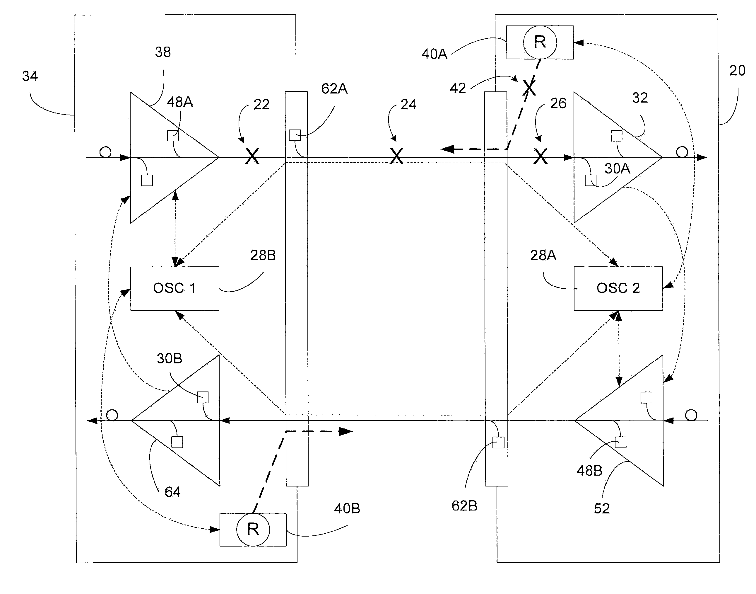
[0028]According to the preferred embodiments of the present invention, each emitting light source, be it a laser, a Raman pump, or an EDFA, has a dedicated detection mechanism at the transmitting and / or receiving end (as appropriate for the communications system in question) that can unambiguously detect presence / absence of that emission source, irrespective of the power levels of other emission sources that may exist on the common fiber. The shutdown sequence is then handled such that APR is first performed on the Raman sources, (potentially non service-affecting), prior to making a determination on service-affecting emission sources (EDFAs). The preferred embodiments of the present invention are also implemented in view of the need to minimize the amount of software required to enact APR. The APR mechanism of the present invention is preferably implemented in hardware and field programmable gate arrays (FPGAs). APR solutions that rely heavily on software implementations, although ...


PUM


Abstract

An automatic optical power management system for use with an optical communications system includes a light source residing in a first circuit pack and adapted to emit light at a nominal power level only absent receipt of an indicator signifying a loss of signal resulting from a fiber discontinuity relating to the first optical fiber, wherein the nominal power level is of sufficient magnitude to violate laser safety guidelines in the event of the fiber discontinuity. A redundant detection system includes a first optical detector residing in the first circuit pack, and a second optical detector residing in a second circuit pack that is optically adjacent to the first circuit. A redundant response system communicates an indicator signifying loss of signal from the first and second optical detectors to the light source upon detection of loss of signal by either detector.

Description

FIELD OF THE INVENTION[0001]The present invention generally relates to optical communications systems and particularly relates to automatic optical power management in a wavelength division multiplexed optical communications system.BACKGROUND OF THE INVENTION[0002]Automatic power management in optical communications systems in general, and Automatic optical Power Reduction (APR) in particular, is a challenge that others have attempted to overcome with varying degrees of success. The need for automatic optical power reduction arises primarily due to safety considerations. In particular, intensity of light exiting a severed optical fiber can easily damage eyesight of individuals not wearing eye protection.[0003]Two competing considerations, speed and reliability, complicate the challenge of providing automatic power reduction. On one hand, optical power needs to be automatically reduced in less than one second after a fiber has been severed in order to maximize safety. On the other ha...

Claims


Application Information

Patent Timeline
IPC IPC(8): H04B10/08H04J14/02
CPCH04B10/077H04B10/07955H04J14/0221H04J14/0226H04J14/0227
Inventor PASSIER, CHRISATKINSON, DAVIDKRENTZ, CARLKRISHNASWAMY, MADHUCHAUVIN, JEAN GUYROBINSON, ANDREWNAGARAJAN, RAJKUMAR
Owner ALTERA CORP
Why Eureka
Try Eureka