Suspension arm

a suspension arm and arm technology, applied in the direction of resilient suspensions, vehicle springs, vehicle components, etc., can solve the problems of reducing the space of the passenger compartment, affecting the straight line stability, and reducing the suspension performance, so as to achieve the effect of reducing the weight of the suspension arm, reducing the width, and reducing the deflection and deformation

Inactive Publication Date: 2007-08-28
AISIN KEIKINZOKU CO LTD +1
View PDF14 Cites 28 Cited by
  • Summary
  • Abstract
  • Description
  • Claims
  • Application Information

AI Technical Summary

Benefits of technology

[0024]The lower end of the part can be supported corresponding to the shape of the part by gradually changing the interval between the two vertical walls in the portion in which the horizontal rib is removed.
[0046]This allows the thickness corresponding to the outer vertical and the inner vertical wall to be substantially secured, whereby the mounting portion is prevented from being sheared.

Problems solved by technology

When the forces exceed the allowable rigidity limit of the suspension arm, a change in alignment occurs since permanent deformation remains, thereby adversely affecting the straight line stability.
However, when forming the suspension arm by joining steel materials in order to obtain strength (e.g. JP-A-2002-316228), since the cost of joining is high, the weakest coil spring support portion can be reinforced merely by joining.
This poses a problem in which the space of the passenger compartment must be reduced or the suspension performance must be decreased.
Therefore, when forming the suspension arm by extruding an aluminum alloy (e.g. JP-A-2000-225821), it is difficult to form the mounting portions having different shapes if the extruded aluminum alloy has an approximately uniform cross-sectional shape.
However, since a sufficient dimensional accuracy cannot be obtained for the center distance in the bearing portions on the ends for which a particularly high dimensional accuracy is required, it is necessary to provide a number of cutting steps after casting to secure dimensional accuracy, or to inspect casting internal defects, thereby increasing the number of steps and manufacturing cost.
However, the welding method decreases mechanical properties due to a thermal effect, and the riveting method results in insufficient bonding strength.
Therefore, cost is increased and sufficient rigidity and strength cannot be obtained.

Method used


Image

  • Suspension arm
  • Suspension arm
  • Suspension arm

Examples


Embodiment Construction

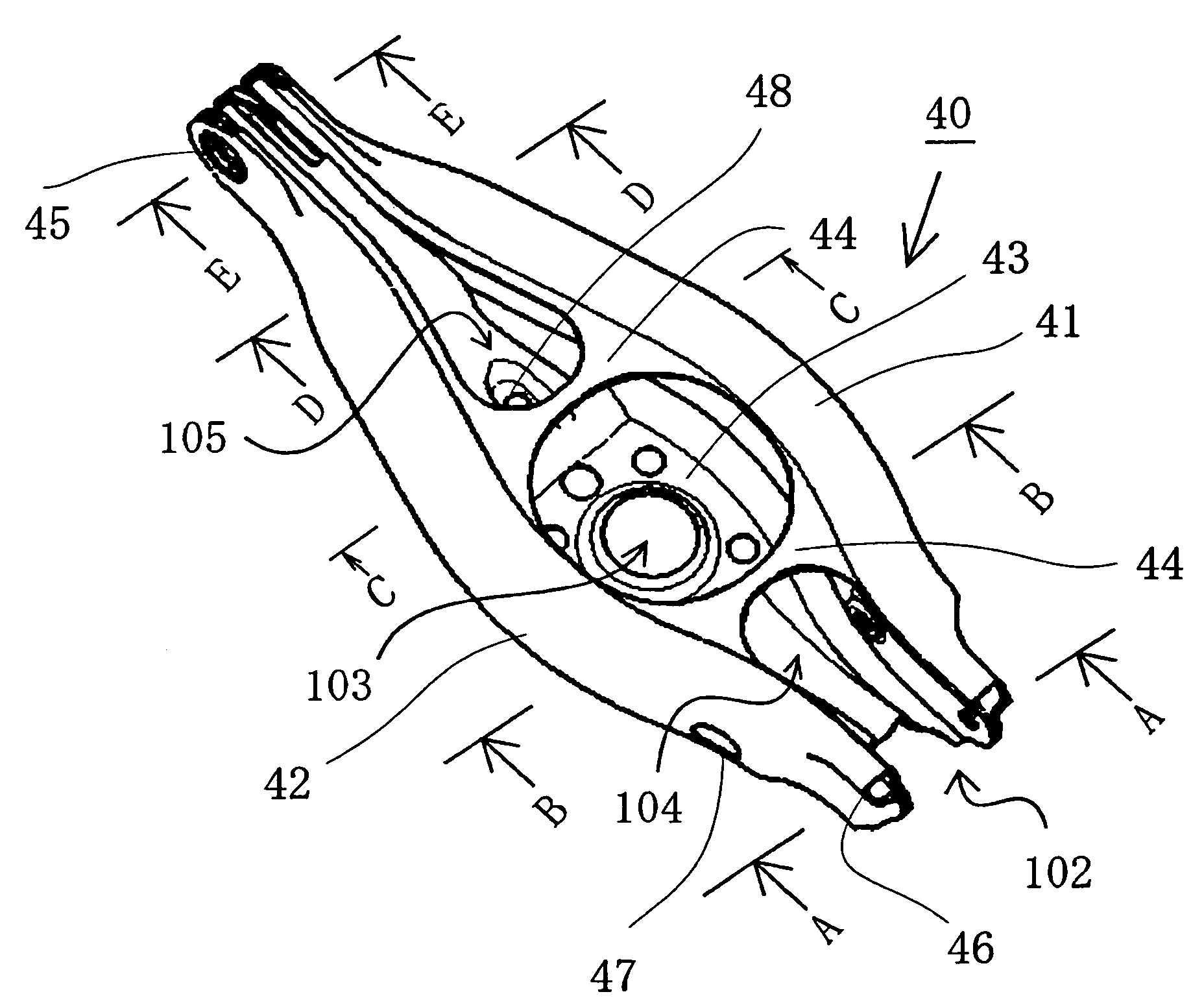
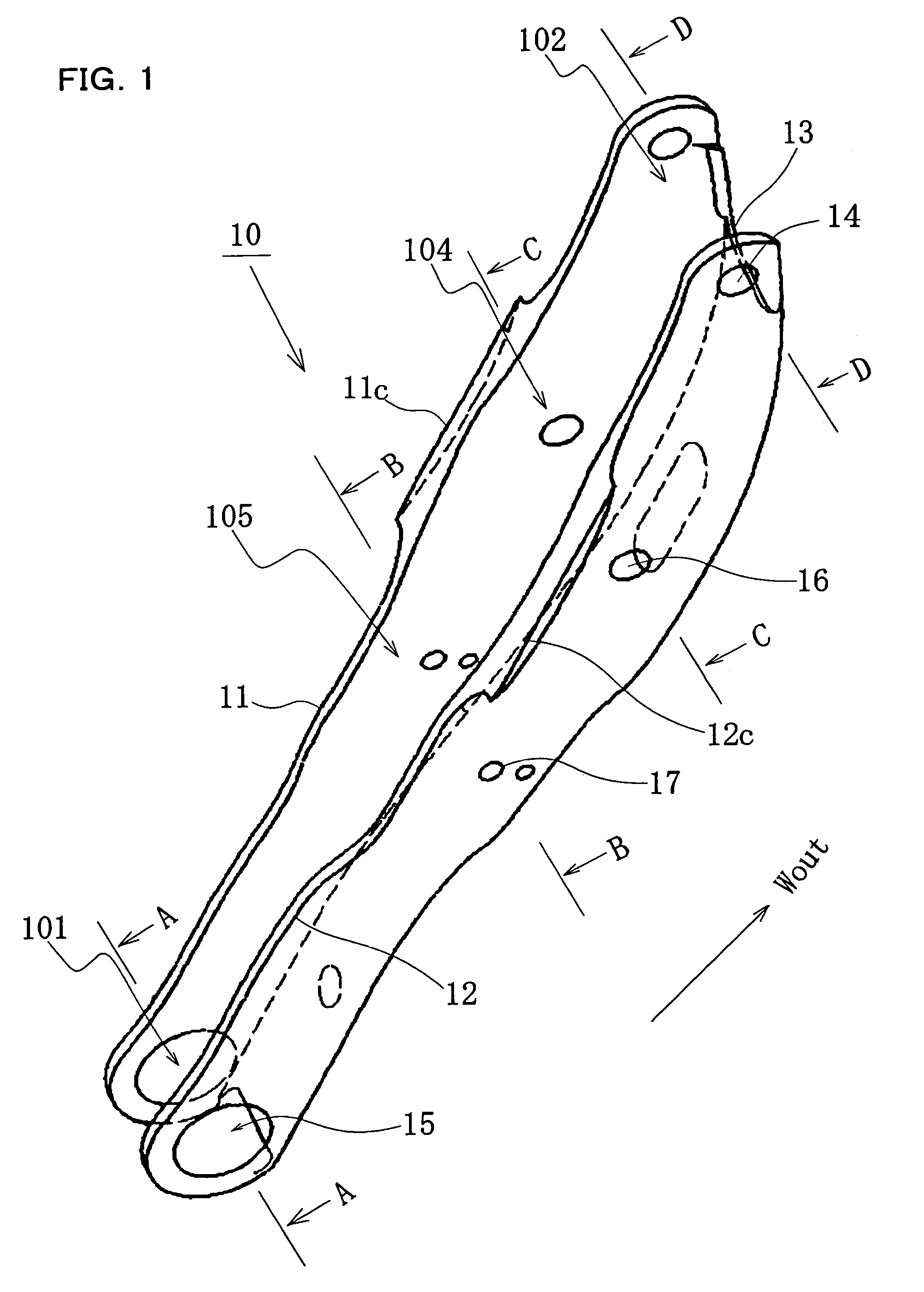
[0072]FIG. 1 is a perspective view of a suspension arm 10 according to the invention.

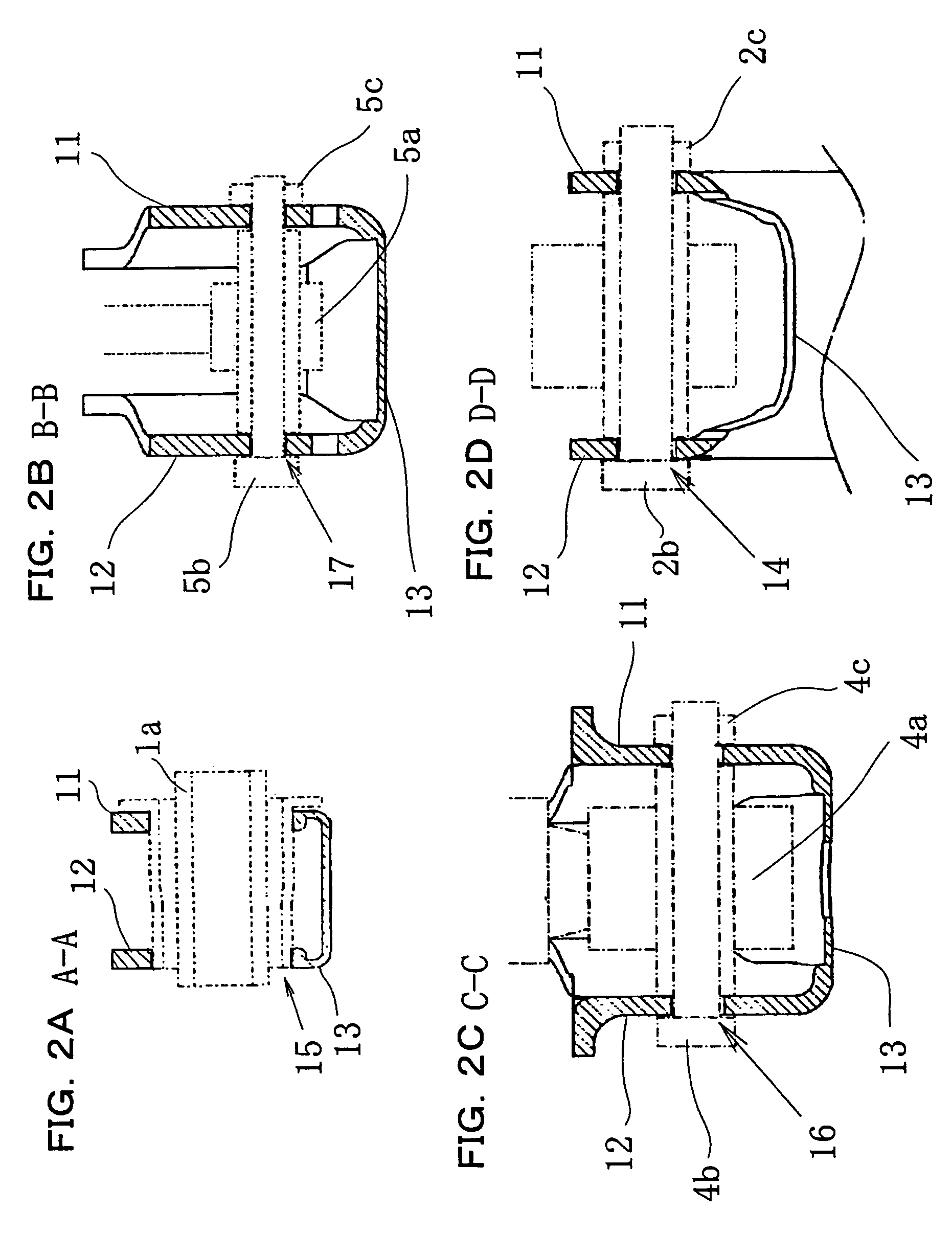
[0073]FIGS. 2A to 2D are cross-sectional views showing part of the suspension arm, which is described together with the assembly drawing of FIGS. 4A and 4B.

[0074]FIG. 2A is a cross-sectional view of a mounting portion 101 for a suspension member 1 (cross-sectional view along the line A-A shown in FIG. 1), FIG. 2B is a cross-sectional view of a mounting portion 105 for a stabilizer link 5 (cross-sectional view along the line B-B shown in FIG. 1), FIG. 2C is a cross-sectional view of a mounting portion 104 for a shock absorber 4 (cross-sectional view along the line C-C shown in FIG. 1), and FIG. 2D is a cross-sectional view of a mounting portion 102 for a axle carrier 2 (cross-sectional view along the line D-D shown in FIG. 1). In FIGS. 2A to 2D, the peripheral parts (e.g. shock absorber 4) of the suspension arm 10 are indicated by the two-dot chain lines and illustrated in an assembled state. FIG. 3 ...


PUM

PropertyMeasurementUnit
widthaaaaaaaaaa
outer diameteraaaaaaaaaa
centrifugal forceaaaaaaaaaa

Abstract

A suspension arm made of an aluminum alloy extruded profile having a portion forming a bottom portion, portions forming at least two vertical walls, and a horizontal rib which connects the two vertical walls, wherein a suspension part lower end support portion is formed between the two vertical walls or at the bottom portion by removing a part of the horizontal rib. It is preferable to gradually change the interval between the two vertical walls in the portion in which the horizontal rib is removed.

Description

CROSS REFERENCE TO RELATED APPLICATION[0001]This application is a continuation of International Patent Application No. PCT / JP2004 / 002662, having an international filing date of Mar. 3, 2004, which designated the United States, the entirety of which is incorporated herein by reference. Japanese Patent Application No. 2003-191526, filed on Jul. 3, 2003, and Japanese Patent Application No. 2003-208732, filed on Aug. 25, 2003, are also incorporated herein by reference in their entirety.BACKGROUND OF THE INVENTION[0002]The present invention relates to a vehicular suspension arm.[0003]As shown in FIG. 24, a centrifugal force G acts toward the right in the direction of the vehicle width when a vehicle turns left. The centrifugal force G acts upon reaction forces F1 and F2 respectively occurring due to the friction between a left tire 2L and a right tire 2R in the direction of the vehicle width and the road, so that a compressive force P1 due to the centrifugal force G and a reaction force ...

Claims


Application Information

Patent Timeline
Patent Type & Authority Patents(United States)
IPC IPC(8): B60G3/02B60G3/20B60G7/00B60G11/14
CPCB60G3/20B60G11/14B60G7/001Y10T29/49622B60G2200/144B60G2202/12B60G2204/1244B60G2204/129B60G2204/143B60G2204/148B60G2204/41B60G2204/416B60G2206/012B60G2206/10B60G2206/162B60G2206/7102B60G2206/8102B60G2206/8103B60G2206/8105
Inventor NUNO, KAZUNOBUAZUCHI, KAZUNARIGYOBU, KIYOHITOSAKUMA, HITOSHI
Owner AISIN KEIKINZOKU CO LTD
Why Eureka
Try Eureka