Gantry for geometrically configurable and non-configurable positron emission tomography detector arrays

a positron emission tomography and geometrically configurable technology, applied in tomography, applications, instruments, etc., can solve the problems of poor image quality, low device efficiency, sticking, etc., and achieve the effect of facilitating patient entry and/or scan

Inactive Publication Date: 2007-08-28
CROSETTO DARIO B
View PDF4 Cites 15 Cited by
  • Summary
  • Abstract
  • Description
  • Claims
  • Application Information

AI Technical Summary

Benefits of technology

[0020]The present invention is directed to a system for geometrically configuring a plurality of detectors for image scanning a patient. The detector barrel of the present gantry system comprises a plurality of essentially planar sensor support rings. Each ring is formed by two semi-elliptical planar support portions, for independent support of detector assemblies or array of detector assemblies. The semi-elliptical planar supports are generally aligned and supported along the longitudinal axis of the barrel, forming two opposing half-barrel shapes. The imaging field...

Problems solved by technology

While particle detection in high energy physics and medical imaging have some common ground, differences between the disciplines are sticking.
However, although the price and performance of the systems from the different manufactures are comparable, one manufacturer's system (Siemens) uses nearly ideal crystal detectors, while in contrast, the other manufacturer's system (General Electric) uses cheaper, lower quality crystal detectors with slower decay time.
Problems inherent in the prior art PET devices include low device efficiency, poor image quality due to, for instance, low spatial resolution, long examination times, and high dosages of radiation to the patient.
These shortcomings result in high examinations costs to the patient, prolonged payback of capital and unsuitability of the current PET technology to adapt to well-patient procedures.
The reason for the prior art PET devices having very small FOVs is because, among other reasons, the capital expense in the detectors.
Even if a PET were configured with a larger FOV, the resulting device would not overcome the shortcoming of the prior art because prior art technologies do not fully exploit the double photon emission phenomenon.
Thus, any increase in the FOV over which the electronics can process the additional photons are wasted.
Clearly utilizing only two out of every 50,000 photons available drastically reduces the data quality and lower resolution images are the result.
A error results from assuming that photons strike the detector at 90 degrees to ...

Method used


Image

  • Gantry for geometrically configurable and non-configurable positron emission tomography detector arrays
  • Gantry for geometrically configurable and non-configurable positron emission tomography detector arrays
  • Gantry for geometrically configurable and non-configurable positron emission tomography detector arrays

Examples


example

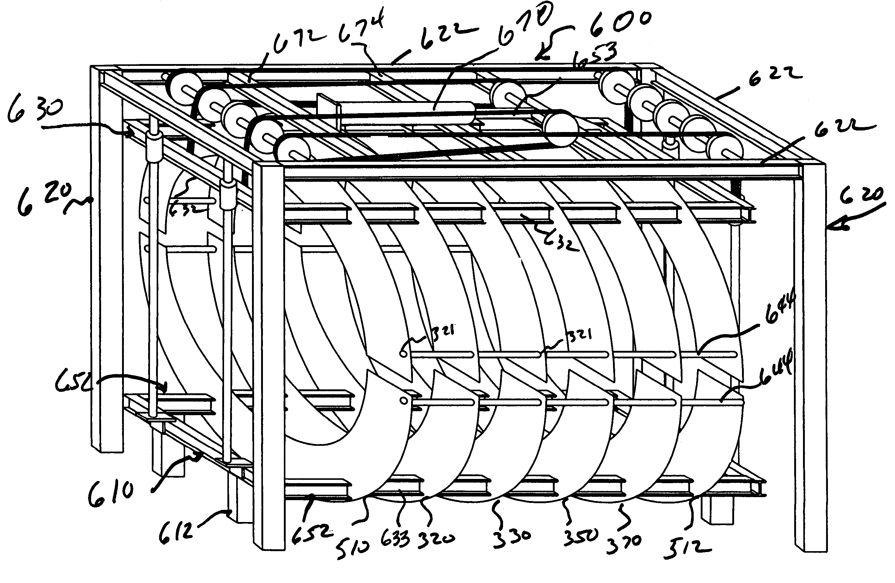
[0044]An exemplary gantry as shown in FIG. 6, which accommodates detectors of different type and shape, was built in approximately one month, working part time and spending only $5,000 in material. FIGS. 3A, 3B, 4, and 5 show the construction of the support of the detector. The rectangular hole in the two semi-arcs is accommodating the I beam of the gantry and is where the weight of the detector is laying. The six round holes (three on the top semi arc and three on the bottom semi arc) are used to accommodate a tube which is solid to the gantry and has a clamp at each semi arc that provides a rigid position of the arc with respect to the gantry.

[0045]An advantage of this construction is that it will help to increase the flexibility in using different types of detector geometries and materials and it lowers the cost of the overall PET because of its simple design. The construction is safe for the patient: e.g., it can accommodate 3-cm thick BGO or LSO detectors assembled in many bloc...


PUM


Abstract

A gantry system for geometrically configuring a plurality of detectors for image scanning a patient comprises a plurality of essentially planar sensor support rings forming a barrel surrounding a central scanning area. Each ring is formed by opposing upper and lower semi-elliptical array supports, and each array support is configured to support a plurality of adjustable detector assemblies. Each array support is adjustable along a longitudinal axis of the barrel, and collectively define an imaging field of view that is configurable by separately adjusting one or more of the array supports. Upper array supports are also preferably moveable in a generally perpendicular direction with respect to longitudinal axis, e.g., to optimize position of the detector assemblies with respect to a patient, to provide for easier patient entry and/or to provide for scans of claustrophobic or obese patients.

Description

CROSS REFERENCES TO RELATED APPLICATIONS[0001]The present application is related to and claims priority from U.S. Provisional Patent Application 60 / 385,140 entitled, “Method And Apparatus For A Low-Radiation, Low-Examination Cost, Three-Dimensional Complete Body Screening,” filed on Jun. 2, 2002. The above identified application is incorporated by reference herein in its entirety.BACKGROUND OF THE INVENTION[0002]1. Field of the Invention[0003]The present invention relates to positron emission tomography (PET). More particularly, the present invention relates to an apparatus for providing geometrically configurable mechanical support PET detector arrays.[0004]2. Description of Related Art[0005]Detectors employed for PET scanning (imaging) are relatively small compared to other detectors used for detecting photons. For instance, PET detectors are about 200 times smaller than the large detectors for high-energy physics and require identification of only one type of particles, the photo...

Claims


Application Information

Patent Timeline
IPC IPC(8): G01T1/161A61B5/05G01T1/29
CPCA61B6/037G01T1/2985
Inventor CROSETTO, DARIO B.
Owner CROSETTO DARIO B
Why Eureka
Try Eureka