Optimized reconfigurable optical add-drop multiplexer architecture with MEMS-based attenuation or power management

a technology of add-drop multiplexers and optical add-drop multiplexers, which is applied in the field of optical communication systems and methods for wavelength division multiplexed (wdm) optical networks, can solve the problems of preventing optimization of key optical parameters of the system, such as passband, and the inability to easily control the spot size on a channel micromirror, so as to achieve the effect of optimizing optical and mechanical characteristics

Active Publication Date: 2007-08-28
CAPELLA PHOTONICS INC
View PDF25 Cites 30 Cited by
  • Summary
  • Abstract
  • Description
  • Claims
  • Application Information

AI Technical Summary

Benefits of technology

[0011]The invention provides new and improved methods and apparatus for wavelength switching of spectral channels of a multi-port, multi-wavelength optical signal that optimize optical and mechanical characteristics, while managing the power or attenuation levels of individual spectral channels of a multi-wavelength optical signal that solve the foregoing problems and disadvantages of known methods and apparatus and afford other significant advantages and benefits.
[0012]These advantages and benefits include: accurate and stable alignment of the ITU channels, high optical passband, optimum coupling of spectral channels to ports, optimum mechanical characteristics and form factor, and accurate and stable control of power or attenuation levels under a broad range of environmental conditions. The invention enables accurate control of the attenuation and power levels of individual channels in a multi-port, multi-channel optical system that affords hitless switching of channels and near “notchless” operation whereby the power levels within the passband of spectral channels can be made approximately the same as the power levels outside the passband between adjacent channels (between the two adjacent mirrors). This enables the transmission of arbitrary optical wavelengths (that need not be confined to any particular ITU grid) regardless of wavelength or spacing between wavelengths so long as the wavelengths are between the upper and lower limits of the wavelength band of interest.
[0016]In other more particular aspects, the channel micromirrors are rotatable about the attenuation axis to steer the output beams off the fiber coupled collimator array. This permits wavelength blocking. In addition, by rotating the biaxial channel mirror about each axis in the proper sequence, the system can achieve hitless reconfiguration.
[0017]Additionally, the invention facilitates maintaining channel alignment of multi-wavelength signals and controlling the beam size and location on the micromirrors. This permits channel micromirror size to be optimized to minimize aerodynamic cross-talk, to control (by design) the mirror resonant frequency, and minimize the required voltage for switching.

Problems solved by technology

Therefore, in some wavelength switches that lack control of the beam size before diffraction and incident to the focusing optics, the spot size on a channel micromirror may not be readily controllable.
For instance, simply accepting the anamorphic beam expansion created by a grating may be insufficient to minimize the spot size on the channel micromirrors to create a high passband.
In general, these factors prevent optimization of key optical parameters of the system, such as passband, and key mechanical parameters of the micromirrors, such as resonant frequency, which is inversely proportional to the mass of the mirror, and aerodynamic interaction between micromirrors, which is approximately proportional to their length to the third power.
However, to substantially reduce the form factor, optical control of the beam sizes throughout propagation is necessary, and a one dimensional anamorphic beam expander is inadequate.
The aforementioned anamorphic beam expansion from the grating or from a prism pair alone does not accomplish this.
During repositioning, the channel micromirror scans the input spectral channel beam across (i.e., “hits”) intermediate ports, which couples unwanted light into the intermediate ports, and causes crosstalk.
However, this approach has the disadvantage of requiring additional components, including a relay lens system to create a focal plane at the liquid crystal array, the liquid crystal array itself, and electronics to control the liquid crystal array.
In addition to the added costs for such additional components, more physical space is needed to accommodate these components, which increases the overall size and complexity of the system.
A disadvantage of this latter approach is that decoupling the spectral channel beam spatially repositions the beam along the switching axis.
Depending upon the physical spacing of adjacent output ports, a portion of the beam may be cross-coupled into an adjacent output port, causing detrimental cross-talk between the ports.
Increasing the physical spacing of the ports to decrease the cross-coupling undesirably increases the physical size of the device.
Furthermore, as will be described in detail later, using this approach it is difficult to accurately control the power output levels of spectral channels due to the sensitivity of the coupling to rotation of the channel mirror about the switching axis.
While each of the aforementioned patents and embodiments known in the art addresses some of the integrated functionality desired in a wavelength selective switch, they fail to achieve a satisfactory level of integration of the desired functionality, performance, or accuracy of control.

Method used


Image

  • Optimized reconfigurable optical add-drop multiplexer architecture with MEMS-based attenuation or power management
  • Optimized reconfigurable optical add-drop multiplexer architecture with MEMS-based attenuation or power management
  • Optimized reconfigurable optical add-drop multiplexer architecture with MEMS-based attenuation or power management

Examples


Embodiment Construction

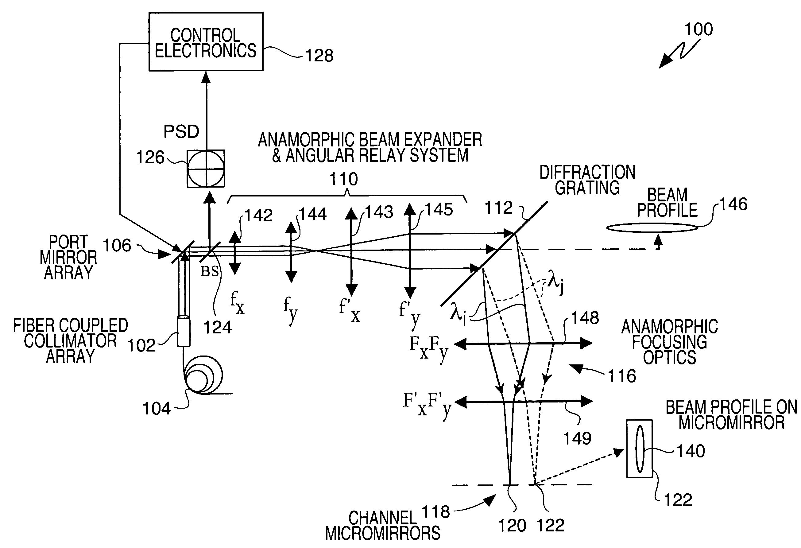
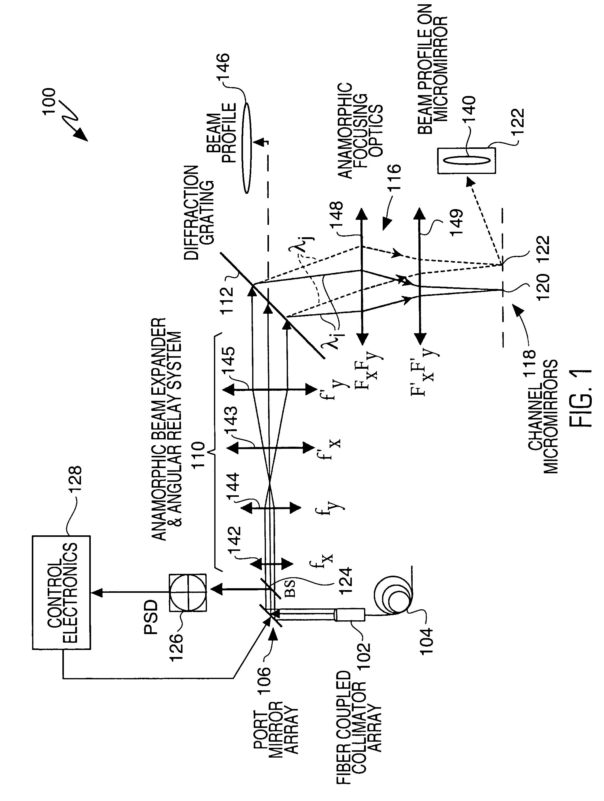
[0029]This invention is particularly applicable to wavelength selective switches (WSS) as used, for example, in reconfigurable optical add-drop multiplexers (ROADMs) permitting dynamic network reconfiguration and enabling management of the power or attenuation of individual spectral channels of a multi-wavelength (multi-channel) optical signal, such that signals can be readily added to or dropped from the network. It will become apparent, however, that this is illustrative of only one utility of the invention

[0030]FIG. 1 is a diagrammatic view that illustrates the architecture of a portion of a wavelength selective switch 100 in accordance with the invention. One or more wavelength selective switches having an architecture as shown in the figure and configured as ADD or DROP modules, may be combined in a ROADM at a node of a wavelength division multiplexed (WDM) optical network, for example. As shown, WSS 100 may comprise a fiber collimator array 102 which provides a plurality of in...


PUM


Abstract

A wavelength selective switch architecture for ROADMs for switching the spectral channels of a multi-channel, multi-wavelength optical signal between input and output ports employs a biaxial MEMS port mirror array for optimal coupling efficiency and ITU grid alignment, an anamorphic beam expander for expanding input optical signals to create an elongated beam profile, a diffraction grating for spatially separating the spectral channels, an anamorphic focusing lens system, an array of biaxial elongated channel MEMS micromirrors, a built-in Optical Channel Monitor, and an electronic feedback control system. The bi-axial channel micromirrors are rotatable about one axis to switch spectral channels between ports, and are rotatable about an orthogonal axis to vary the coupling of the spectral channel to an output port and control attenuation of the spectral signal for complete blocking or for a predetermined power level. The architecture affords hitless switching, near notchless operation, ITU channel alignment, high passband, stability over a broad temperature range, and minimum insertion loss through the optimal optical coupling efficiency enabled by the feedback control system.

Description

BACKGROUND [0001]This application relates generally to optical communications systems and methods for wavelength division multiplexed (WDM) optical networks, and more particularly to wavelength selective switch systems and methods having optimized optical performance for switching and managing the power of individual spectral channels of a multi-channel optical signal.[0002]Multi-channel optical signals of the type to which the invention pertains comprise a plurality of spectral channels, each having a distinct center wavelength and an associated bandwidth. The center wavelengths of adjacent channels are spaced at a predetermined wavelength or frequency interval, and the plurality of spectral channels may be wavelength division multiplexed to form a composite multi-channel signal of the optical network. Each spectral channel is capable of carrying separate and independent information. At various locations, or nodes, in the optical network, one or more spectral channels may be droppe...

Claims


Application Information

Patent Timeline
Patent Type & Authority Patents(United States)
IPC IPC(8): G02B6/26H04B10/27H04B10/29H04B10/40H04B10/43H04B10/50H04B10/60
CPCG02B6/29311G02B6/29313G02B6/29383G02B6/29395G02B6/356G02B6/3588G02B6/3594G02B6/2706G02B6/3512
Inventor DAVIS, JOSEPH E.GARRETT, MARK H.TREMAINE, BRIANDARLING, MICHAEL
Owner CAPELLA PHOTONICS INC
Why Eureka
Try Eureka