Controlling evaporative emissions in a fuel system

a fuel system and evaporative emission technology, applied in the direction of fuel injection apparatus, charge feed system, non-fuel substance addition to fuel, etc., can solve the problems of evaporative loss, evaporation of liquid fuel into, evaporative loss the most, etc., to reduce or prevent evaporative emissions from the fuel system

Inactive Publication Date: 2007-09-04
WALBRO ENGINE MANAGEMENT
View PDF23 Cites 35 Cited by
  • Summary
  • Abstract
  • Description
  • Claims
  • Application Information

AI Technical Summary

Benefits of technology

[0012]According to exemplary embodiments, a method and a fuel system are provided for controlling evaporative emissions of volatile fuel. According to the method, liquid fuel is supplied from a fuel tank into a carburetor during operation of an engine. Also, during shutdown of the engine, liquid fuel is stopped from flowing into the carburetor, and liquid fuel is drained out of the carburetor into a receptacle. According to the system, the fuel tank contains liquid fuel, and the carburetor receives the liquid fuel from the fuel tank during operation of the engine and mixes air with the liquid fuel for supply to the engine. Moreover, during shutdown of the engine, a valve actuation device stops flow of fuel from the fuel tank to the carburetor and the carburetor is drained of fuel to reduce or prevent evaporative emissions from the fuel system.
[0014]According to another exemplary embodiment, a carburetor includes a body, a float that is carried by the body and that is movable about a pivot axis. A fuel bowl is carried by the body for containing fuel and includes a closed end that has an inside bottom surface sloped generally downwardly away from the pivot axis. The closed end of the fuel bowl also has a low-lying collection area and a fuel drain outlet disposed substantially at the low-lying collection area to enable substantially complete drainage of fuel out of the fuel bowl.
[0018]According to yet another embodiment, a method of reducing evaporative emissions from a carburetor is provided wherein the carburetor includes a fuel bowl, a fuel inlet passage in communication with the fuel bowl, an inlet valve to valve the inlet fuel passage, a float pivotable about a float pivot axis, and a fuel nozzle jet to communicate fuel within the fuel bowl to a fuel nozzle. The method comprises minimizing at least one of the size of the inlet fuel passage or the lateral distance between float pivot axis and at least one of the vertical axis of the inlet fuel passage or the inlet valve, and maximizing at least one of the fuel contact surface area of the float or the lateral distance between the float pivot axis and a fuel buoyancy force associated with the float, wherein the volume of fuel within the fuel bowl is substantially minimized.
[0019]At least some of the objects, features and advantages that may be achieved by at least certain embodiments of the invention include providing a method, fuel system, carburetor, and pumps that enable a reduction in the emission to the atmosphere of unburned fuel vapors, permit a carburetor fuel bowl to be drained during engine shutdown, improve control of fluid flow in a fuel system, can be actuated in a variety of ways including at least manual and powered or automatic, can open and close various valves for controlled venting of a fuel tank and controlled supply of fuel to a carburetor, yield a compact construction and arrangement, do not require active operator intervention to reduce evaporative emissions, are adaptable to a wide range of applications, are of relatively simple design and economical manufacture and assembly, rugged, durable, reliable and have a long, useful life in service.

Problems solved by technology

Volatile fuel emissions generally include hot soak losses, running losses, and diurnal losses.
Hot soak and diurnal losses result from emission of liquid or vaporous fuel and include permeation losses and evaporative losses.
Evaporative losses occur when liquid fuel evaporates into hydrocarbon vapor and escapes into the atmosphere.
Evaporation of liquid fuel into fuel vapor is usually due to volatility of the fuel, vibration of the fuel tank and sloshing of the fuel therein, and temperature fluctuations of the fuel.
Evaporative losses most often occur 1) when fuel vapors in a fuel tank are vented to the atmosphere, and 2) when fuel vapors in a carburetor are vented or otherwise escape to the atmosphere.
But ground-supported equipment typically uses float-bowl carburetors, which become flooded under such positive tank pressures.
While such a system works well, the added cost of the carbon canister and float valve is prohibitive in many applications.
Moreover, the equipment may be placed in a storage enclosure with limited or no ventilation, wherein the temperature may fluctuate over a twenty-four hour period from a daytime high exceeding 160 degrees Fahrenheit to a nighttime low of 60 degrees Fahrenheit.
Unfortunately, however, diaphragm carburetors are not practical for all engine applications because they tend to have limited fuel metering capabilities, thereby leading to operational instability with certain types of engines.
In contrast, ground-supported equipment typically have engines with float-bowl carburetors that usually have relatively higher fuel metering capabilities to accommodate infinitely variable throttle settings between idle and WOT, but tend to yield relatively higher evaporative emissions for several reasons.
Second, diaphragm carburetors are not continuously supplied with fuel from the fuel tank when the engine is not operating.
In this case, fuel may completely evaporate from within the diaphragm carburetor, but is not continuously replenished with fuel from the fuel tank.
Hence, hot soak and diurnal losses in a float bowl carburetor are also increased due to these vaporization-replenishment-vaporization cycles.
Unfortunately, conventional combination rubber duck bill and umbrella valves, typically associated with diaphragm carburetor fuel systems, tend to suffer from hysteresis.
Thus, such valves are not capable of repeatably holding a tank pressure close enough to a predetermined threshold pressure.

Method used


Image

  • Controlling evaporative emissions in a fuel system
  • Controlling evaporative emissions in a fuel system
  • Controlling evaporative emissions in a fuel system

Examples


first exemplary embodiment

of a Mechanical Pump

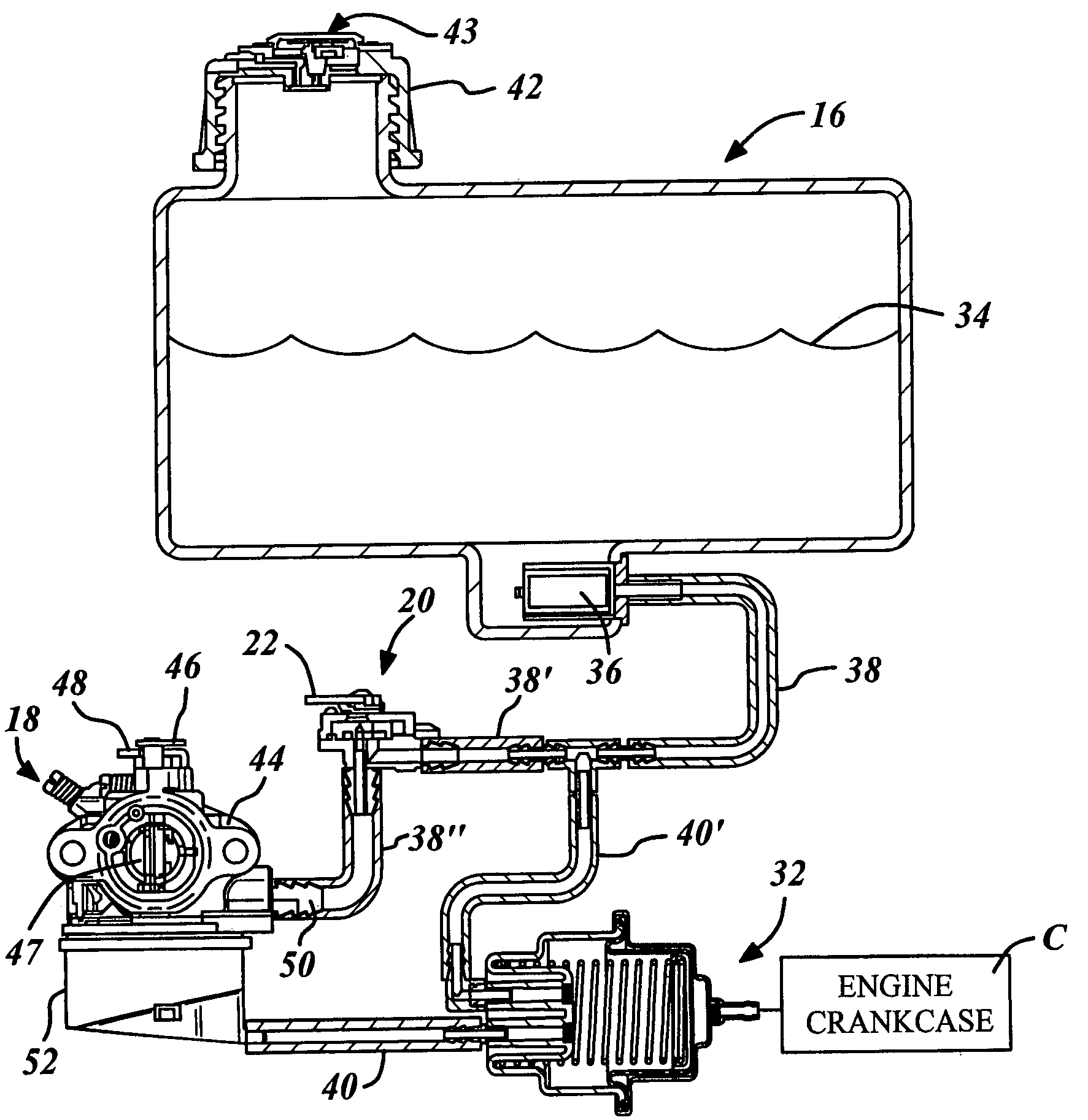
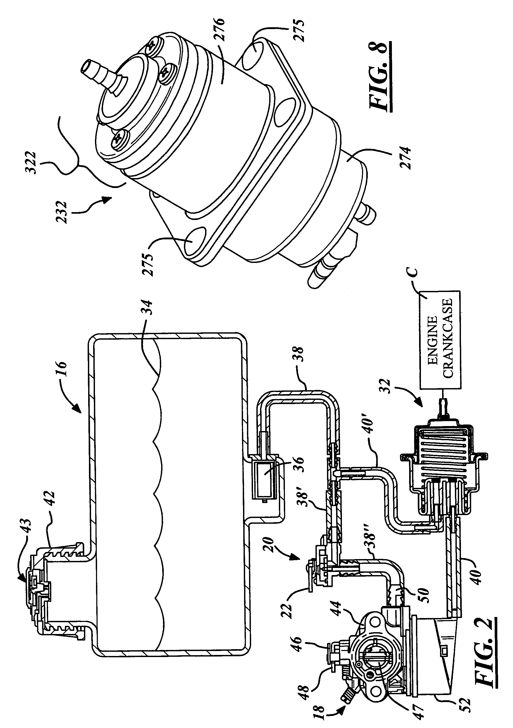
[0088]The fuel is removed from the carburetor fuel chamber or bowl 52 preferably using a fuel transfer and storage unit, such as the mechanical accumulator or pump 32 of FIG. 2. It is contemplated that any suitable type of pump could be used including an electrically-actuated pump (“electric pump”), pneumatic mechanical pumps, plunger style mechanical pumps, and the like. As also shown in FIGS. 5 and 6, the pump 32 includes a housing 74 and a cover 76 attached to the housing 74, such as by a circumferential crimp joint as shown, to define an interior 78. The housing 74 and cover 76 are preferably stamped or machined from metal, molded from a polymeric material, or the like.

[0089]A diaphragm 80 is disposed within the interior 78 and is sealingly engaged between the cover 76 and housing 74 by the crimp joint to divide the interior 78 into a fuel reservoir 82 on a reservoir side of the diaphragm 80 for carburetor bowl drainage, and an actuation chamber 84 on an actu...

second exemplary embodiment

of a Fuel System

[0126]FIGS. 27 through 30 illustrate in block diagram, another exemplary embodiment of a fuel system that generally depicts many of the features of the previous embodiments and that includes some additional features. This embodiment is similar in many respects to the previously described embodiments and like numerals between the embodiments generally designate like or corresponding elements throughout the several views of the drawing figures. Accordingly, some common subject matter may not be repeated in detail herein below.

[0127]The block diagrams of FIGS. 27 through 30 generally include an engine-powered apparatus or equipment 1012 having a combustion engine 1014 for powering the equipment 1012 and a fuel system for storing and distributing fuel to the engine 1014. The fuel system includes a fuel tank 1016 for storing fuel, fuel lines or fluid paths for carrying fuel, a carburetor 1018 for mixing air with the fuel, and a combined fuel pump and valve actuation devic...

third exemplary embodiment

of a Fuel System

[0139]FIG. 31 schematically illustrates another exemplary embodiment of a fuel system that generally depicts many of the features of the previous embodiments and that includes some additional features. This embodiment is similar in many respects to the previously described embodiments and like numerals between the embodiments generally designate like or corresponding elements throughout the several views of the drawing figures. Accordingly, some common subject matter may not be repeated in detail herein below.

[0140]Referring now to FIG. 31, a gravity draining fuel system includes a fuel tank 1216, a carburetor 1218 generally elevated with respect to the fuel tank 1216, a pneumatically-actuated pump 1231 positioned generally beneath the fuel tank 1216 in fluid communication between the carburetor 1218 and the fuel tank 1216, and a four-way fitting 1233 positioned generally beneath the fuel tank 1216 in fluid communication between the fuel tank 1216 and carburetor 1218...


PUM


Abstract

Methods and fuel systems to reduce evaporative emissions of a volatile fuel. A fuel tank contains fuel, a carburetor mixes air with the fuel from the fuel tank, and a plurality of fluid paths route fuel amongst and / or between the fuel tank and the carburetor. A valve actuation device stops flow of fuel in one or more of the plurality of fluid paths and the carburetor is adapted to be drained of fuel during engine shutdown to reduce or prevent evaporative emissions from the fuel system. The carburetor is preferably designed so as to minimize a volume of fuel contained therein.

Description

FIELD OF THE INVENTION[0001]This invention relates generally to volatile fuel storage and delivery systems for internal combustion engines, and more particularly to evaporative emission controls adapted for use with a carburetor.BACKGROUND OF THE INVENTION[0002]A fuel storage and delivery system typically includes a fuel tank and a carburetor that are adapted for use in small, internal combustion engine-powered apparatuses. These apparatuses comprise a large consumer market of popular lawn, garden, and marine products, which include hand-held equipment such as hedge trimmers, grass trimmers, and chainsaws and ground-supported equipment such as snow-blowers, generators, water pumps, power washers, sprayers, garden tractors, rototillers, and lawnmowers and marine equipment like inboard and outboard motors and auxiliary generators. In recent years, such products have been improved to reduce engine exhaust emissions, but now emphasis is being placed on improving these products to reduce...

Claims


Application Information

Patent Timeline
Patent Type & Authority Patents(United States)
IPC IPC(8): F02M5/10F02M5/12
CPCF02M5/14F02M7/12F02M17/04F02M25/0836F02M25/089F02M37/0023
Inventor WOODY, JOHN C.
Owner WALBRO ENGINE MANAGEMENT
Why Eureka
Try Eureka