Caster angle measurement system for vehicle wheels

a technology of measurement system and caster, which is applied in the direction of measurement devices, instruments, surveying and navigation, etc., can solve the problems of reducing the accuracy of caster angle measurement, wasting time, and wasting time, so as to save considerable operator time, reduce errors, and save time

Active Publication Date: 2007-09-04
BURKE E PORTER MACHINERY
View PDF10 Cites 19 Cited by
  • Summary
  • Abstract
  • Description
  • Claims
  • Application Information

AI Technical Summary

Benefits of technology

[0016]The present invention provides significant advantages over prior known methods of measuring and calculating caster and caster angle for steerable wheel assemblies on vehicles. The present invention avoids any direct contact with the vehicle including the wheel assembly through the use of an image capture device such as a video camera and light source thereby saving considerable operator time and reducing errors based on operator measurement with the measuring tools. The image capture device is positioned in a predetermined position, and does not require movement or repositioning to measure the caster angle. In addition, the present invention requires significantly less time for obtaining the caster angle of a wheel assembly because of several reasons including the rapid camera response, the elimination of human measurement, the elimination of contact with the wheel assembly during measurement, and simultaneous measurement with other operations or measurements. Thus, operator labor required is reduced and the cost of measuring and setting or auditing caster and caster angle is lowered. Further, the invention is durable and avoids the use of moving parts and tools subject to wear thereby further reducing costs involved in caster measurement and adjustment. These and other objects, advantages, purposes and features of the invention will become more apparent from a study of the following description taken in conjunction with the drawings.

Problems solved by technology

In the past, caster angle was measured using various direct and indirect methods which were time consuming, labor intensive, and less accurate than desired.
Direct caster angle measurement methods require human operators or mechanisms to place measurement tools in contact with the vehicle and are subject to placement error and wear.
This indirect method allows measurement error in each of the steering wheel positions as well as operator error and / or mechanical wear.
If the toe and camber of the wheel are measured by contact methods, then additional error can be encountered.
Moreover, the indirect measurement method requiring measurements at various steering wheel positions requires significant cycle time to perform thereby causing greater expense.

Method used


Image

  • Caster angle measurement system for vehicle wheels
  • Caster angle measurement system for vehicle wheels
  • Caster angle measurement system for vehicle wheels

Examples


Embodiment Construction

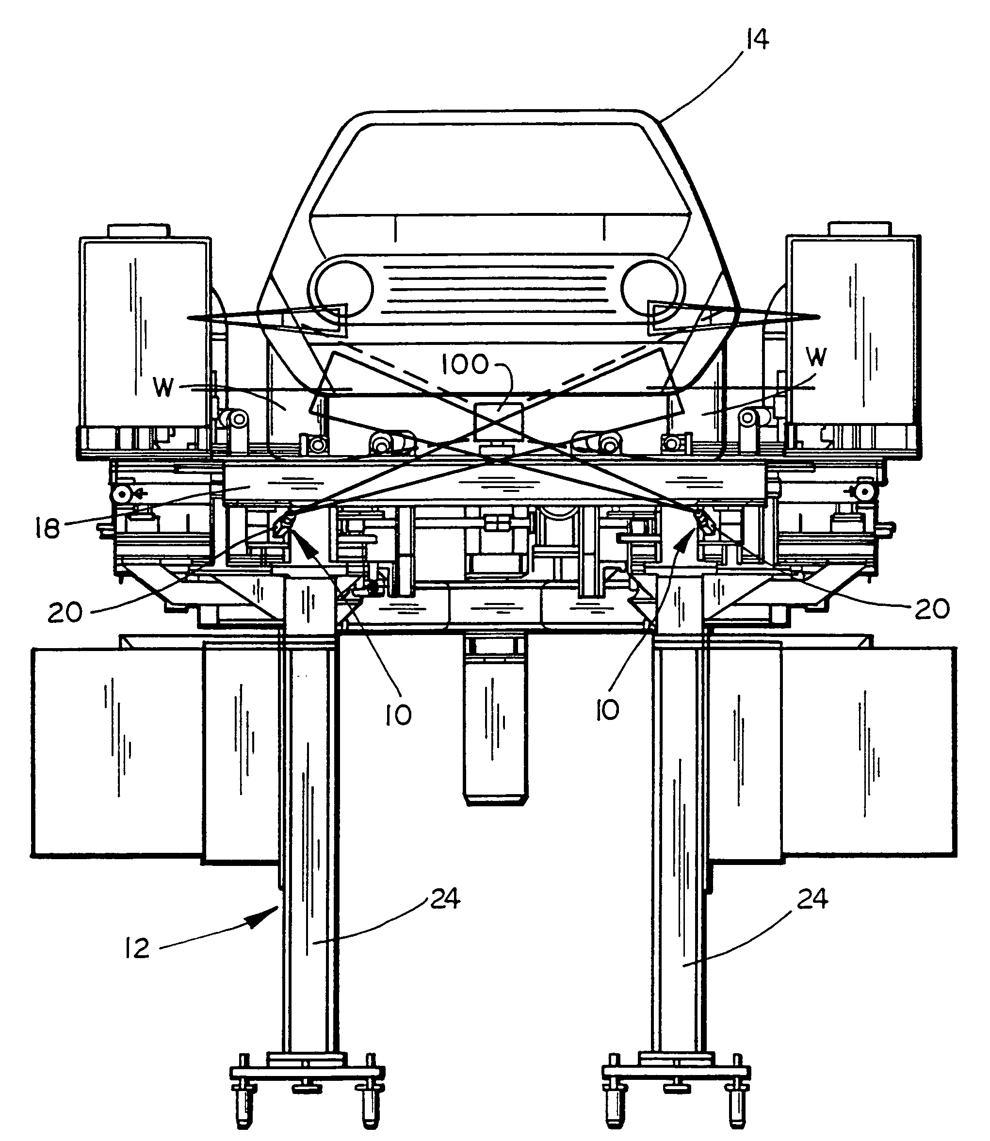
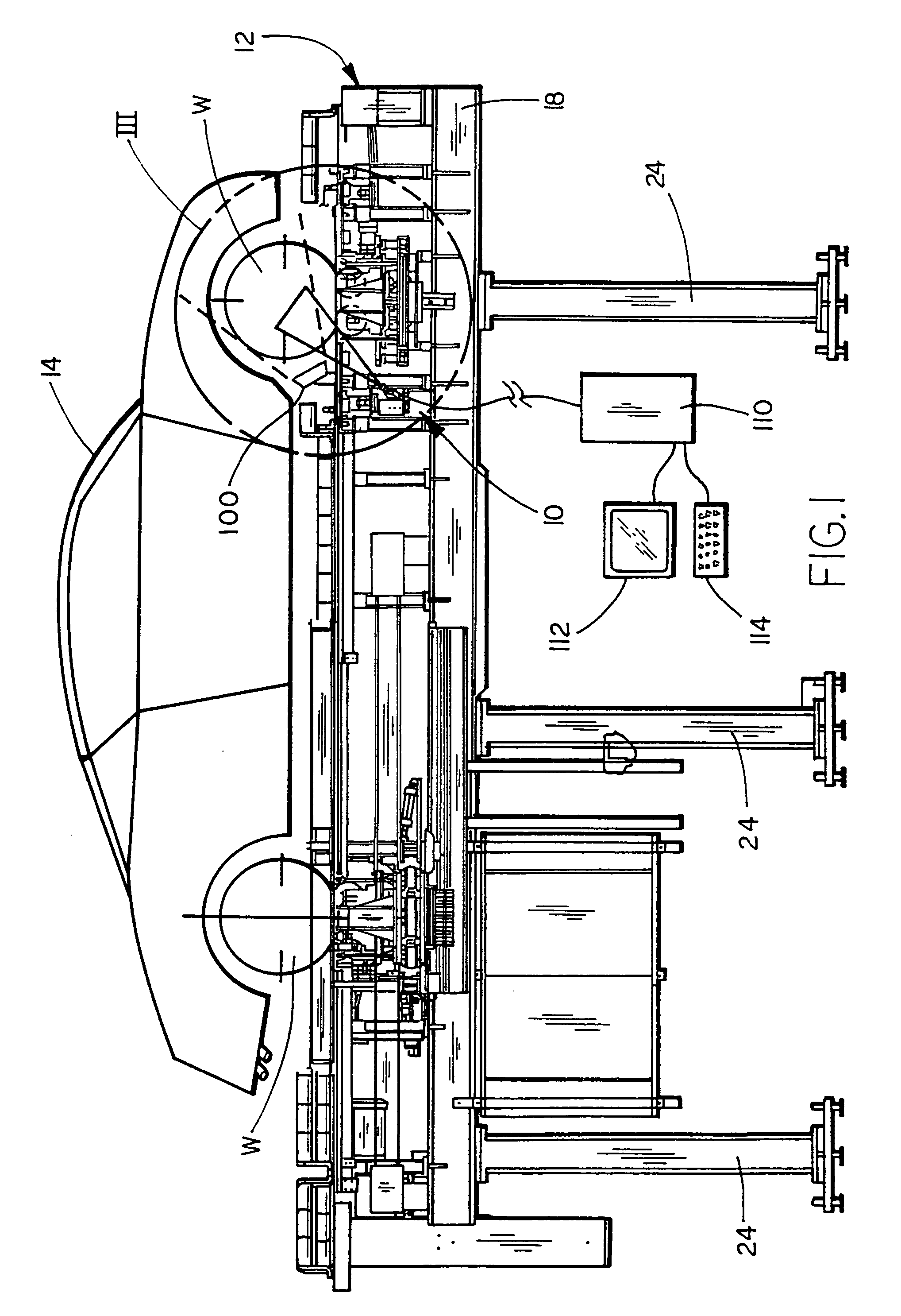
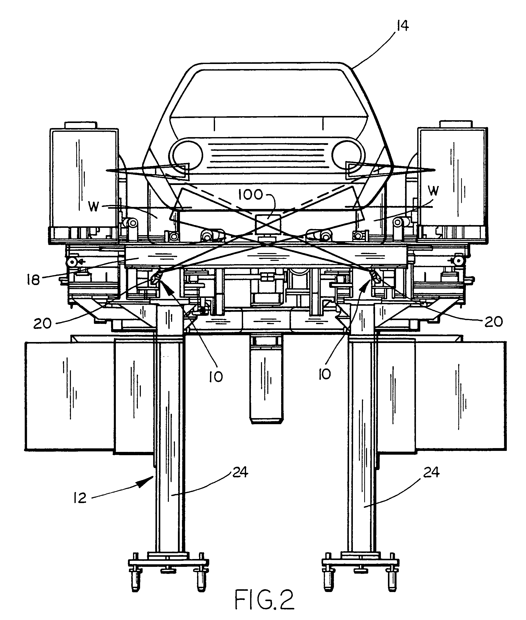
[0029]Referring now to the drawings in greater detail, FIGS. 1-3 illustrate a preferred embodiment of the non-contact caster angle measurement system 10 of the present invention incorporated in a vehicle alignment machine 12 which supports a vehicle 14 for various alignment functions. As shown in FIGS. 1 and 2, alignment machine 12 preferably includes a pair of the caster angle measurement systems 10 each including an image capture device such as a video camera 20 having a lens 22 and supported on an adjustable image capture device support such as a camera support 30 (FIG. 3). Preferably, each caster angle measurement system 10 is supported below the top surface 16 above which vehicle 14 is supported on alignment machine 12 with the cameras 20 positioned on supports 30 for viewing upwardly and across the machine toward the opposite side to the inside surface of the opposing vehicle wheel assembly as shown in FIG. 2. In addition, measurement system 10 includes one or more light sourc...


PUM


Abstract

An apparatus and method is provided for measuring the caster angle of a steerable wheel assembly without contact with the vehicle. An image capture device, preferably a CCD type video camera or sensor, views a vehicle wheel mounting and steering assembly that is illuminated by a light source. Information from the captured image is transmitted to a computer based control, such as a computer or processor, that determines the angle of a preformed line or preselected physical features on the wheel assembly in the captured image, and determines the caster angle of the steering axis based on the fixed angular relationship of the line or physical features to the steering axis that is stored or accessed by the control. Preferably, the image capture device is mounted below the vehicle on a vehicle alignment machine that supports the vehicle.

Description

CROSS REFERENCE TO RELATED APPLICATION[0001]This application claims priority on U.S. Provisional Application Ser. No. 60 / 515,734, filed Oct. 29, 2003, the disclosure of which is hereby incorporated by reference herein.FIELD OF THE INVENTION[0002]This invention relates to measurement systems for vehicle wheels and, more particularly, to a measurement system for determining the caster angle of a steerable vehicle wheel on a vehicle using an image capture device such as a closed circuit video camera system that does not require any contact with the vehicle.BACKGROUND OF THE INVENTION[0003]Steerable wheel assemblies for vehicles pivot around an inclined axis known as the steering axis, the position of which is determined by the joints and suspension components of the wheel and steering assembly. Proper positioning and alignment of a steerable wheel, and especially a front wheel of a vehicle, may require the setting of toe, camber angle and caster angle. Toe is the angle between the vehi...

Claims


Application Information

Patent Timeline
Patent Type & Authority Patents(United States)
IPC IPC(8): G01B11/26
CPCG01B11/2755G01B2210/28
Inventor LAWRENCE, JON DOZDEMIR, MUNIR TSYBESMA, HILBRAND JLEHMAN, JAMES R
Owner BURKE E PORTER MACHINERY
Why Eureka
Try Eureka