Data processing apparatus, image processing apparatus, and method therefor

Active Publication Date: 2007-09-04
CANON KK
View PDF15 Cites 45 Cited by
  • Summary
  • Abstract
  • Description
  • Claims
  • Application Information

AI Technical Summary

Benefits of technology

[0022]The present invention has been proposed to solve the conventional problems, and has as its object to provide a data processing apparatus which can facilitate addition / modification on a data processing module (processor) basis by making an I / F for each data processing module versatile, and a method for the apparatus.
[0028]In addition, according to the present invention, in order to solve the above problems, it is an object to provide an image processing apparatus, in which each type of image processing for input image is divided into a plurality of processing blocks, each processing block is formed into a module, and data transfer among the respective modules is performed through a shared memory, thereby making an I / F for each image processing module versatile, facilitating addition / modification on an image processing module basis, and reducing unnecessary buffers, memories, and processing, and a method for the apparatus.
[0042]It is another object of the present invention to provide an image processing apparatus which can increase the image processing speed with respect to overall image data in executing image processing for blocked image data, and reduce the capacity of a memory required for image processing, and a method for the apparatus.
[0044]In addition, the image processing apparatus according to the present invention is further comprising rasterization means for rasterizing the blocked image data, and resizing means for reducing a block size, wherein rasterization is performed after the block size is reduced.

Problems solved by technology

According to the method disclosed in Japanese Patent Laid-Open No. 2001-109656, however, since data read / write addresses are generated by one functional block, the processor side must control to avoid read / write contention, resulting in complicated control.
In addition, a plurality of data processing modules (processors) cannot be pipelined, and data must always be transferred through the memory interface.
Furthermore, since a buffer memory is provided on the memory interface and shared among a plurality of processors, it is difficult to optimize the buffer memory.
If the number of data processing modules (processors) increases, not only the arbiter must be modified, but also a control circuit and buffer memory must be added, resulting in difficulty in making a modification.
When a module that needs to simultaneously acquire a plurality of (discontinuous) data, e.g., a resizing or filter module, is to be added, the above address generating circuit as well as the buffer memory becomes complicated.
The method disclosed in Japanese Patent Laid-Open No. 9-116660 has a drawback that many buffer memories are required in proportion to the number of image processing modules.
In addition, an enormous local memory is required to cope with an arbitrary image size.
According to the method disclosed in Japanese Patent Laid-Open No. 9-116660, it is impossible to replace some function after the completion of hardware.
In this case, if the above series of processing modules is implemented by hardware, it is impossible to replace only the RGB conversion module with another processing (software processing).
As a consequence, the series of processing modules including the RGB conversion module is wasted.
If a critical defect is caused in some module, all the associated processing modules become unusable.
According to the conventional image processing method, however, since image processing is performed after rasterization, it takes much time to perform overall image processing, and many memories for processing which are required for image processing must be mounted in the image processing apparatus.
This increases the access time.

Method used


Image

  • Data processing apparatus, image processing apparatus, and method therefor
  • Data processing apparatus, image processing apparatus, and method therefor
  • Data processing apparatus, image processing apparatus, and method therefor

Examples


first embodiment

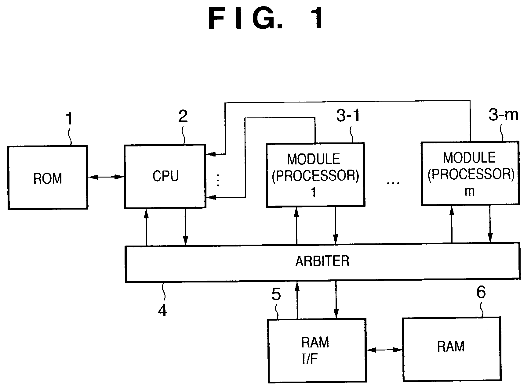
[0093]The first embodiment of the present invention will be described in detail below with reference to the accompanying drawings. FIG. 1 is a block diagram showing an example of the arrangement of a data processing apparatus according to the first embodiment of the present invention.

[0094]Referring to FIG. 1, reference numeral 1 denotes a ROM storing programs and the like; 2, a CPU for controlling the data processing apparatus; 3-1 to 3-m (m is an integer equal to or more than 1), m data processing modules (processors); 6, a RAM; 4, an arbiter for arbitrating access to the RAM 6 between data processing modules 3-1 to 3-m; and 5, a RAM interface unit 5. Although the RAM 6 in this embodiment is shared by the CPU 2 and the respective data processing modules 3-1 to 3-m, the CPU 2 may have another RAM.

[0095]The processing operation of the data processing apparatus having the above arrangement will be described next.

[0096]The CPU 2 receives data to be processed through an I / O or the like...

second embodiment

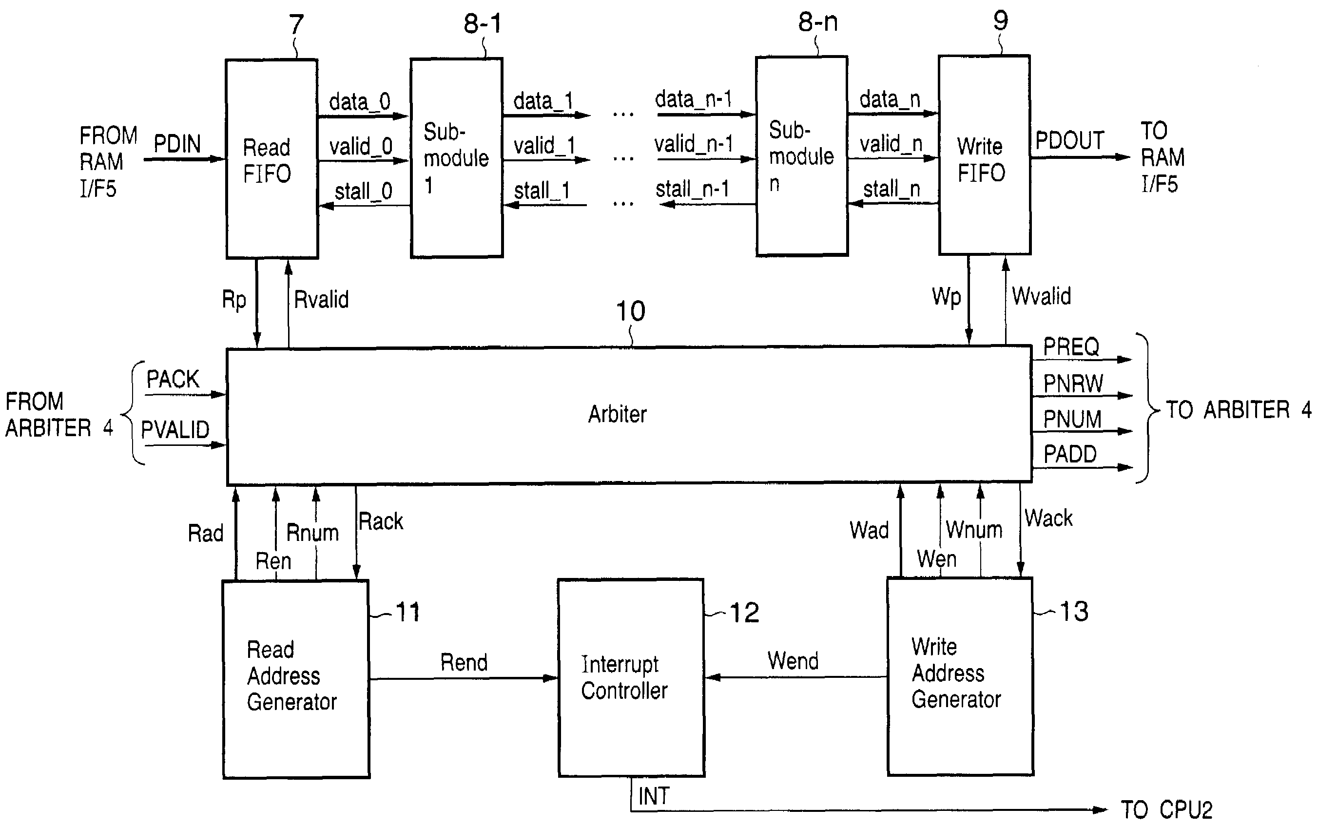
[0157]FIG. 9 is a block diagram for explaining the detailed internal arrangement of each module of a data processing apparatus according to the second embodiment of the present invention. Referring to FIG. 9, reference numerals 19-1 to 19-i (i is an integer equal to or more than 1) denote read FIFOs; 20, an arbiter; 21-1 to 21-n, sub-modules; 22-1 to 22-i, read address generators; and 23, a read interrupt controller. Only a portion different from the first embodiment will be described below.

[0158]Assume that in this embodiment, the sub-module 21-1 handles data stored at a plurality of discontinuous addresses. For this reason, each module in this embodiment includes a plurality of read FIFOs 19-i and a plurality of read address generators 22-i corresponding to the respective read FIFOs 19-i. If, for example, data from a plurality of lines are simultaneously required as in a case of block encoding of an image, a FIFO and read address generator are provided in correspondence with each ...

third embodiment

[0167]FIG. 10 is a block diagram for explaining the detailed internal arrangement of each module of a data processing apparatus according to the third embodiment of the present invention. Referring to FIG. 10, reference numeral 24 denotes a read buffer; 25-1 to 25-n, sub-modules; and 26, a read address generator. Only a portion different from the first and second embodiments will be described below.

[0168]Assume that in this embodiment, as in the second embodiment, a sub-module 25-1 handles data stored at a plurality of discontinuous addresses. Assume, however, that in this embodiment, there is predetermined regularity between the above discontinuous addresses as in block encoding of an image.

[0169]A CPU 2 sets a configuration register in a module 3 to set a read start address and read end address in the read address generator 26 and set an read enable signal Ren.

[0170]The arbiter 10 detects a free space Rp of the read buffer 24 and the read enable signal Ren from the read address ge...


PUM


Abstract

There are provided a data processing apparatus which makes an I / F for data processing modules (processors) versatile to facilitate addition / modification on a data processing module basis in accordance with processing contents, an image processing apparatus, and a method for the apparatuses. A data processing module (3) includes a read address generator (11), read FIFO (7), write address generator (13), write FIFO (9), and arbiter (10) and is connected to a host arbiter (4) through a 1-channel port. The read address generator (11) and write address generator (13) generate interrupts upon acceptance of final access requests so as to control activation of each data processing module (8-1-8-m) in accordance with the state of each data processing module in interrupt processing. Note that data transfer among the respective data processing modules is performed on a RAM (6).

Description

FIELD OF THE INVENTION[0001]The present invention relates to a data processing apparatus which performs data processing by exchanging data through a memory, an image processing apparatus, and a method for these apparatuses.BACKGROUND OF THE INVENTION[0002]In general, a processor can access a memory through a memory interface to read out data to be processed or write processed data. This processor generates an internal address for the memory interface, and the memory interface generates appropriate control signals for accessing data corresponding to the internal address. These control signals activate a specific memory cell corresponding to the internal address.[0003]Assume that the processor has a 23-bit internal address A[22:0]. The memory interface generates, for a DRAM type memory, a page number from A[22:12], a bank selection signal from A[11:10], a column number from A[9:2], and a word selection signal from A[1:0]. The memory interface generates, for an SRAM type memory, an SRA...

Claims


Application Information

Patent Timeline
IPC IPC(8): G06K9/54G06T1/20
CPCG06T1/20G06T3/4092Y10S707/99936Y10S707/99932
Inventor ISHIKAWA, HISASHIMISE, RYOKO
Owner CANON KK
Why Eureka
Try Eureka