Apparatus for low cost lightning detection

a lightning detection and low-cost technology, applied in the field of low-cost detection of lightning, can solve the problems of aggregating the two channels, power consumption of more complex processors, and practical problems, and achieve the effect of reducing the cost, quick determining the strength of a strike, and quick determining the strength of a fast lookup schem

Inactive Publication Date: 2007-09-04
OUTDOORS TECH
View PDF4 Cites 9 Cited by
  • Summary
  • Abstract
  • Description
  • Claims
  • Application Information

AI Technical Summary

Benefits of technology

[0004]In accordance with the invention, an apparatus for low cost lightning detection employs an apparatus for quickly determining the strength of fast lookup scheme for quickly determining the strength of a strike at any orientation from the detector and its 2 orthogonal antennas.
[0005]Accordingly, it is an object of the present invention to provide an improved method of determining the strength of a strike independent of its orientation relative the antennas.
[0006]It is a further object of the present invention to provide an improved method that allows a lower cost and lower power processor to be used for the detection of lightning.
[0007]Accordingly, the object of the invention relates to a lightning detector system that monitors the lightning strike information in real time using a low cost microprocessor that has a single analog to digital channel and no hardware floating point math capability. The advantage of this invention is it allows a small, low cost lightning detector to be developed with long battery operation. Long battery operation allows a smaller unit with a lower operating cost.

Problems solved by technology

Some practical problems arise when aggregating the two channels.
This results in the use of floating point libraries when summing operations, such as the square root of the sum of the squares require a much longer time periods than required by a real time lighting detection system.
Additionally, the power consumption of more complex processors capable of performing the summing operation would lessen the battery life of a portable, low cost product.

Method used


Image

  • Apparatus for low cost lightning detection
  • Apparatus for low cost lightning detection
  • Apparatus for low cost lightning detection

Examples


Embodiment Construction

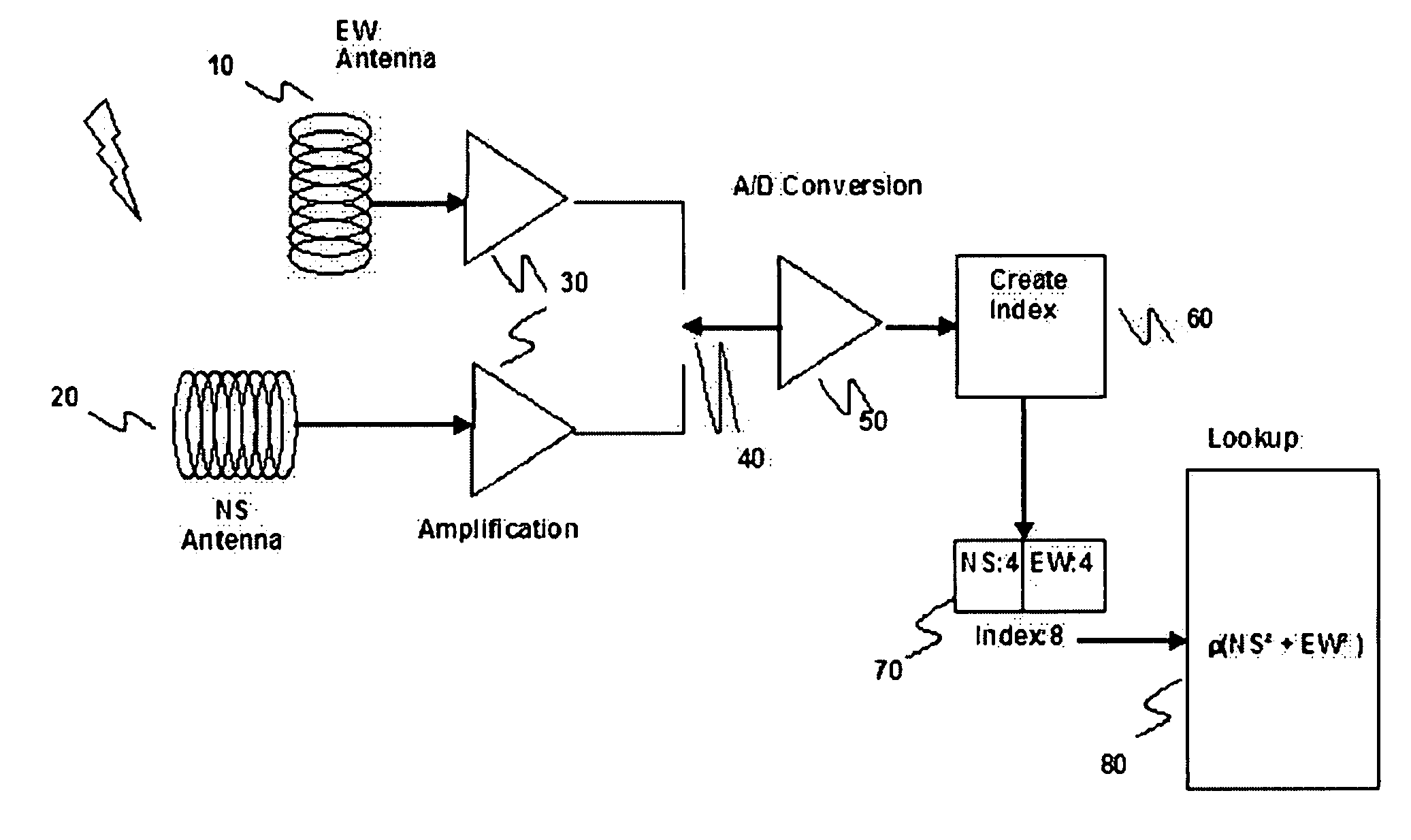
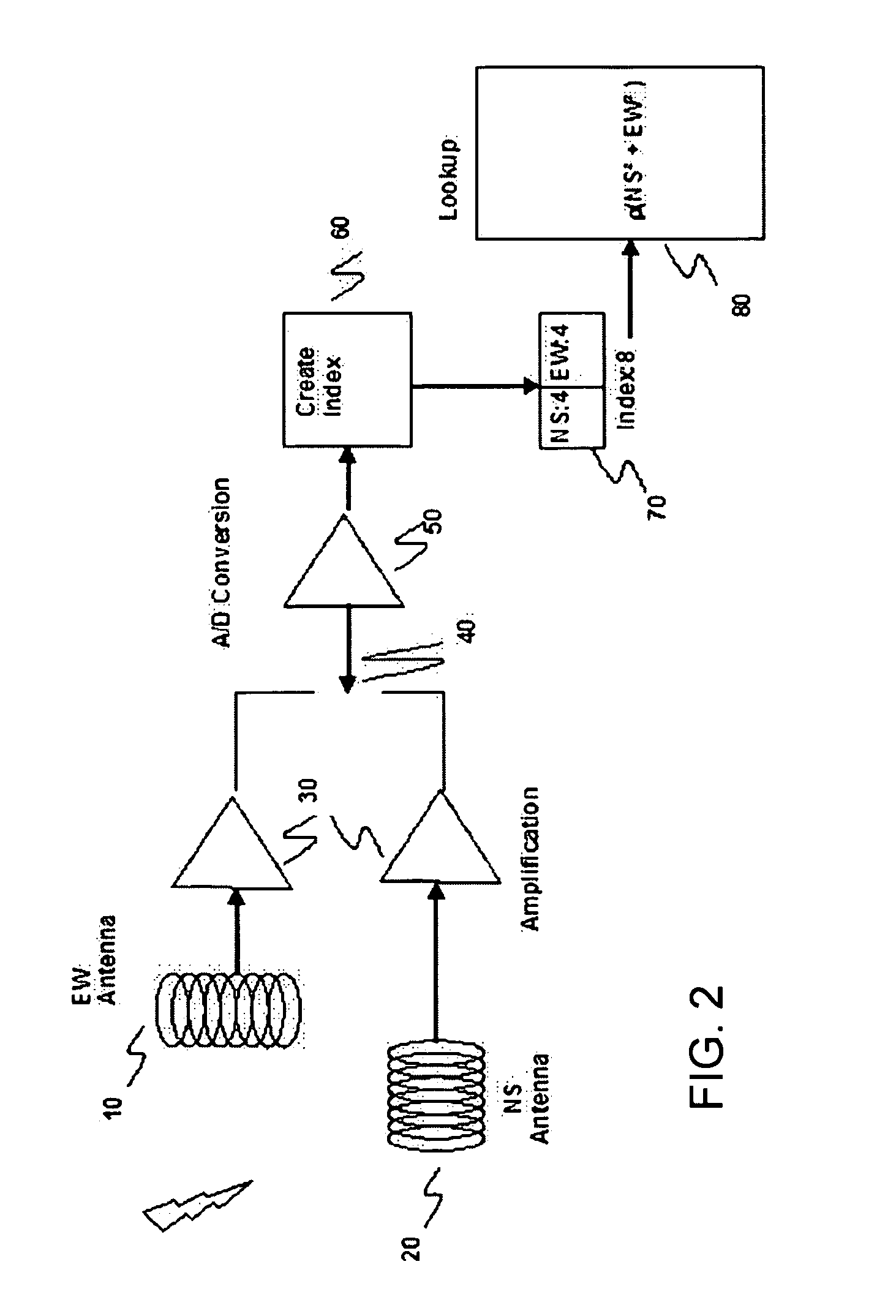
[0013]The system according to a preferred embodiment of the present invention comprises 2 orthogonal antennas, signal amplification, an 8 bit A / D converter, a lookup table with 256 entries, and the ability to form an index into the lookup table.

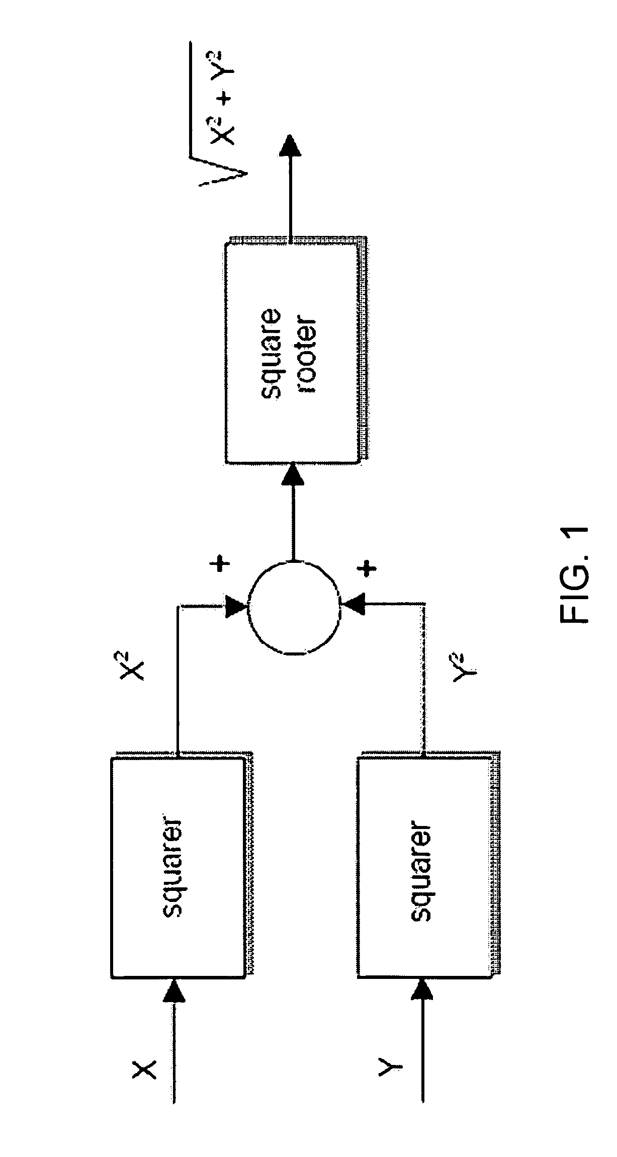
[0014]Referring to FIG. 2, a block diagram that illustrates the preferred embodiment, antennas 10 (EW, east-west) &20 (NS, north-south) are oriented horizontal and perpendicular to each other. Signal amplification is provided by amplifiers 30. The signal, NS or EW, to be measured is switched into the A / D converter 50 by switch 40, which alternately connects to either the NS or the EW amplifier output. In operation, as soon as one side, NS or EW is sampled, the other side is sampled thereafter. The results of the conversion are used to create an index 60 into a pre-computed lookup table 80. The table is created in advance on a more powerful computer by computing the resultant strength for combinations of individual orientation strengths.

[0015]...


PUM


Abstract

A lightning detector system monitors the lightning strikes requires a real-time detection and processing system. A real-time processing system requires the use of a high-speed processor with floating-point math capability and multiple analog to digital channels. The cost, power and size requirements of such a system make it difficult to develop a low cost, pocket size lightning detector with long battery life. This invention provides a method of detecting and ranging lightning strikes using an inexpensive eight-bit processor with a single A / D channel and without floating point hardware.

Description

[0001]This application claims priority of U.S. provisional patent application Ser. No. 60 / 659,929, filed Mar. 10, 2005.BACKGROUND OF THE INVENTION [0002]This invention relates to the low cost detection of lightning. Most lightning detectors detect the electromagnetic field of the return stroke of a cloud to ground strike and indicate the approximate distance to the strike. Previous developments in the field of lightning detection include ranging systems that display the distance to lighting strikes (U.S. Pat. No. 3,715,660 Ruhnke) and devices that use CRTs to display the azimuth and distance from the user (U.S. Pat. No. 4,023,408, Ryan et al).[0003]The use of 2 perpendicular, horizontal coils for detecting the electromagnetic signal of lightning strikes is common practice. This allows one antenna to detect north-south (NS) strikes and the other to detect east west (EW) strikes. To determine the strength of a strike that is not perfectly perpendicular to the coils requires a summing ...

Claims


Application Information

Patent Timeline
Patent Type & Authority Patents(United States)
IPC IPC(8): G01W1/00G06F11/30
CPCG01W1/16Y02A90/10
Inventor KAHKOSKA, JAMES ANTHONY
Owner OUTDOORS TECH
Why Eureka
Try Eureka