Method for making equivalent circuit model of passive element, simulator, and storage medium

a technology of equivalent circuit model and simulator, applied in the field of deriving equivalent circuit model of passive components, can solve the problems of difficulty in estimating the electric characteristics of a complicated electronic circuit, the efficiency of electronic circuits using circuit simulators, and the inability to meet the requirements of electrical characteristics

Active Publication Date: 2007-09-04
PANASONIC CORP
View PDF5 Cites 5 Cited by
  • Summary
  • Abstract
  • Description
  • Claims
  • Application Information

AI Technical Summary

Benefits of technology

[0008]By a method for deriving an equivalent circuit model, a circuit simulato

Problems solved by technology

Regarding the electronic devices, it is very difficult to estimate electric characteristics of a complicated electronic circuit when the circuit is being designed.
However, these conventional equivalent circuit models do not have satisfying accuracy.
Therefore,

Method used


Image

  • Method for making equivalent circuit model of passive element, simulator, and storage medium
  • Method for making equivalent circuit model of passive element, simulator, and storage medium
  • Method for making equivalent circuit model of passive element, simulator, and storage medium

Examples


exemplary embodiment 1

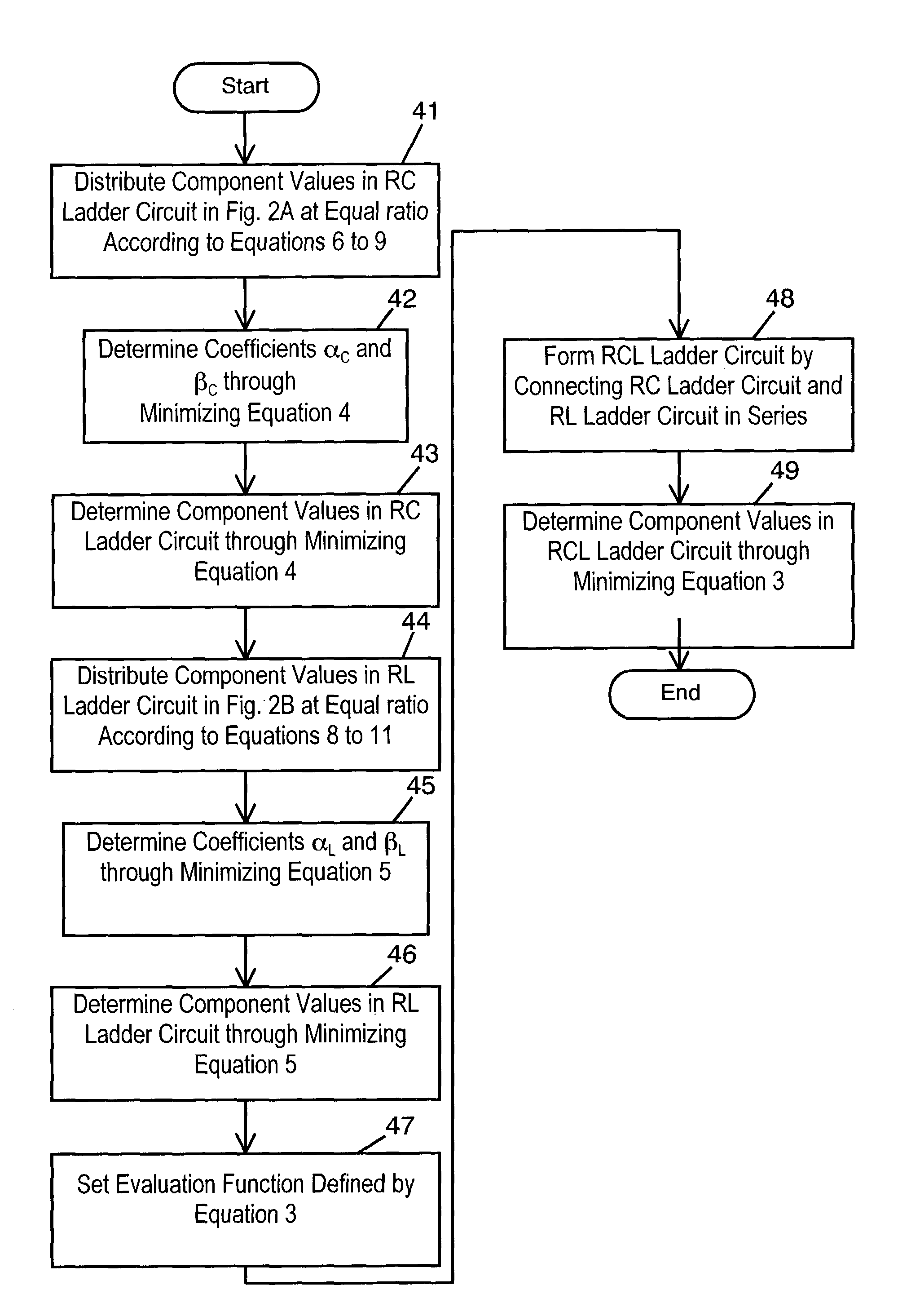
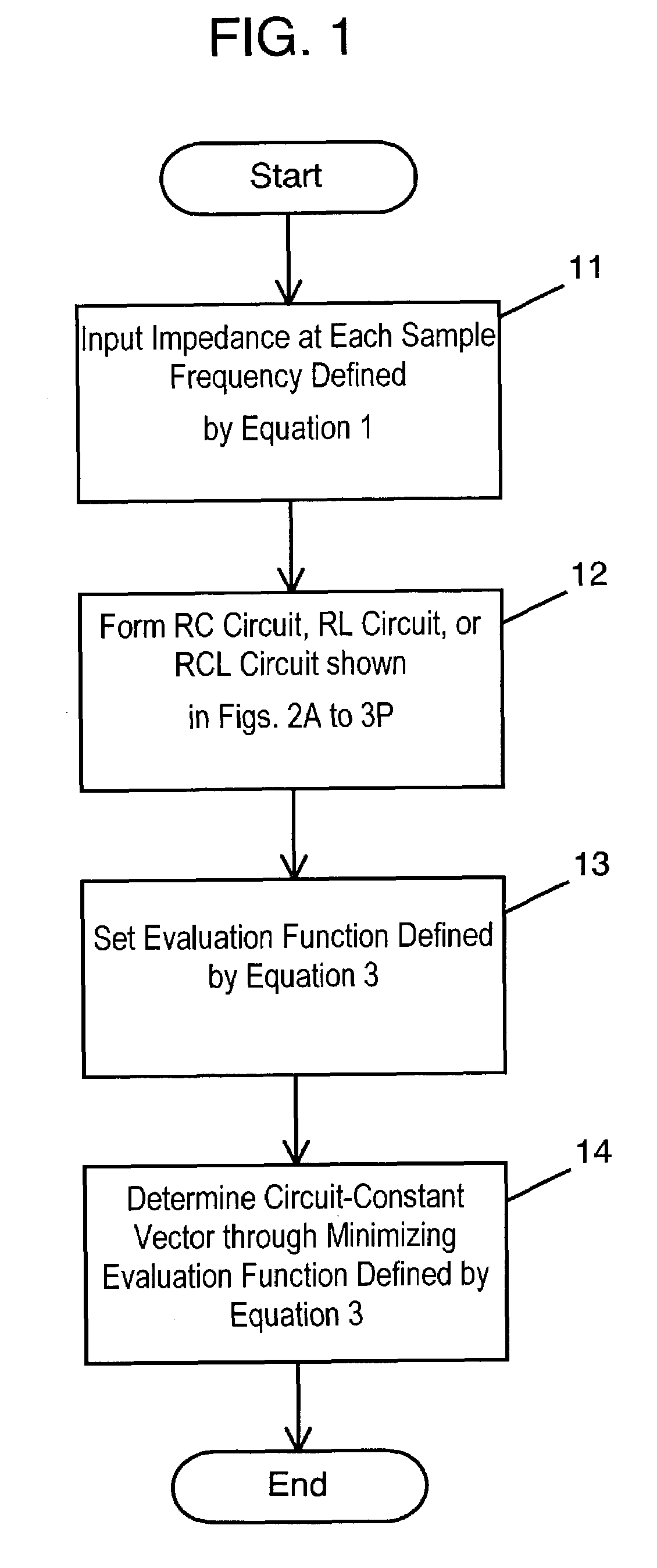
[0042]FIG. 1 is a flowchart of processes in a method for deriving an equivalent circuit model of a capacitor according to an exemplary embodiment. Impedances as sampled values for frequencies shown by equation 1, which will be described later, are provided. (Step 11). Using frequency-independent resistance (R), capacitance (C), and inductance (L), one of an RC circuit consisting of the resistor and the capacitor, an RL circuit consisting of the resistor and the inductor, and an RCL circuit consisting of the RC circuit and the RL circuit connected in series is formed as an equivalent circuit model representing a circuit enabling a simulation in a time domain (step 12). An evaluation function defined by equation 3, described later, is set with equations 1 and 2 (step 13). A circuit constant vector is determined by minimizing equation 3 (step 14).

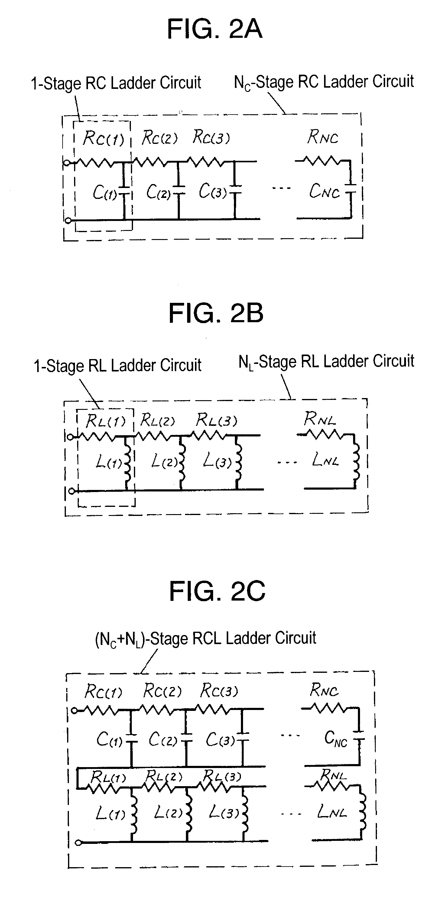
[0043]FIG. 2A through FIG. 2C show circuit diagrams of the equivalent circuit models of a capacitor according to the embodiment. FIG. 2A illu...

exemplary embodiment 2

[0088]In a method of deriving an equivalent circuit model of exemplary embodiment 2, an RCL circuit is formed as an equivalent circuit model wherein the real part R(fn) of impedance becomes minimum value R0 at sample frequency fm(fm≠f1 and fm≠fn), in step 12 of exemplary embodiment 1, and evaluation function in a low frequency region fm+1≦fn≦fm is calculated according to:

[0089]A(P->)=∑n=1N⁢a⁡(RM⁡(fn,P->),XM⁡(fn,P->),R⁡(fn)-xR0,X⁡(fn))(Equation⁢⁢4)

where (0≦x≦1), instead of the evaluation function defined by equation 3 in step 13. Further, factors x and d are set as x=½ and d=2 in calculation of evaluation function in a high frequency region fm+1≦fn≦fN according to

[0090]B(P->)=∑n=1N⁢b(RM(fn,P->),XM(fn,P->),R⁡(fn)-(1-x)⁢R0,X⁡(fn))(Equation⁢⁢5)

where 0≦x≦1. That is,

[0091]A⁡(P->)=∑n=1m⁢a⁢(RM⁡(fn,P->),XM⁡(fn,P->),R⁡(fn)-R0 / 2,X⁡(fn)),⁢a⁡(RM,XM,R,X)=⁢cR⁢RM-(R-R0 / 2)2Rd+cX⁢XM-X2Xd+⁢cZ⁢ZM-Z2Zd,B⁢(P->)=∑n=m+1N⁢b⁡(RM(fn,P->),XM⁡(fn,P->),R⁡(fn)-R0 / 2,X⁡(fn)),andb...

exemplary embodiment 3

[0092]An RC circuit is formed as an equivalent circuit model in which a real part R(fn) of impedance becomes minimum value R0 at sample frequency of fm (fm=fN) in step 12 of embodiment 1, and an evaluation function in an entire frequency region f1≦fn≦fN is calculated according to:

[0093]A⁡(P->)=∑n=1N⁢a⁡(RM⁡(fn,P->),XM⁡(fn,P->),R⁡(fn)-xR0,X⁡(fn))(Equation⁢⁢6⁢a)

where 0≦x≦1, instead of the evaluation function in step 13. A new RC circuit is then completed by connecting additionally a resistance xR0 in series to the above RC circuit.


PUM


Abstract

A method of deriving an equivalent circuit model for a passive component includes a first step of providing a given frequency characteristic of a capacitor, a second step of forming one of an RC circuit, an RL circuit, and an RCL circuit using frequency-independent resistances (R), capacitances (C) and/or inductances (L), as the equivalent circuit model representing a circuit capable of performing a simulation in a time domain, a third step of composing an evaluation function for evaluating accuracy of the equivalent circuit model formed in the second step, and a fourth step of determining values of the circuit components by minimizing the evaluation function composed in the third step. The method with a simulator adapted for implementing this method and a computer-readable storage medium containing a recorded program, derives the equivalent circuit model for a capacitor. The model is capable of performing a simulation in the time domain using a common procedure not dependent upon types of passive components.

Description

FIELD OF THE INVENTION[0001]The present invention relates to a method for deriving equivalent circuit model of passive components. The invention relates particularly to a method for deriving the equivalent circuit models, a simulator, and a storage medium that are capable of performing simulation in a time domain by a common procedure which is independent from types of the passive components.BACKGROUND OF THE INVENTION[0002]According to trend toward use of high frequencies and high-speed digitization in data communication devices, it has been important recently to perform highly accurate circuit simulation in a time domain of electronic circuits including passive components.[0003]Regarding the electronic devices, it is very difficult to estimate electric characteristics of a complicated electronic circuit when the circuit is being designed. For manufacturing the circuit, a lot of trial is repeated in which an actual prototype assembly of the circuit is made and measured in its elect...

Claims


Application Information

Patent Timeline
IPC IPC(8): G06F17/50G01R25/00
CPCG06F17/5036G06F30/367
Inventor MAESHIMA, HIROYUKIAOSHIMA, YOICHIKOBATAKE, YASUHIROMASUDA, YOJIITO, MAMORU
Owner PANASONIC CORP
Why Eureka
Try Eureka