Method and system for graphically identifying replacement parts for generally complex equipment

a technology for complex equipment and replacement parts, applied in the direction of transportation and packaging, railway auxiliary equipment, instruments, etc., can solve the problems of increasing complexity of equipment, affecting the diagnosis, maintenance and repair of generally complex equipment, and requiring a large amount of time and labor

Inactive Publication Date: 2007-09-04
GENERAL ELECTRIC CO
View PDF64 Cites 44 Cited by
  • Summary
  • Abstract
  • Description
  • Claims
  • Application Information

AI Technical Summary

Problems solved by technology

The diagnosis, maintenance, and repair of generally complex equipment, such as mobile assets including on-road or off-road vehicles, ships, airplanes, railroad locomotives, trucks, and other forms of complex equipment including industrial equipment, consumer appliance equipment, medical imaging equipment, equipment used in industrial processes, telecommunications, aerospace applications, power generation, etc., involves extremely complex and time consuming processes.
However, if the problem is complex and the root cause difficult to discern, the experienced technician may be unable to identify the problem and certainly much less likely to prognosticate problems before they occur.
Various equipment often incorporates diagnostic controls and sensors that report faults when anomalous operating conditions of the equipment arise.
It will be apparent that as the complexity of the equipment increases, the amount of paper needed to describe the equipment to assist with the repair process likewise increases.
Yet another problem with a paper-based system is the variety of field-deployed equipment configurations, each having its own unique techn...

Method used


Image

  • Method and system for graphically identifying replacement parts for generally complex equipment
  • Method and system for graphically identifying replacement parts for generally complex equipment
  • Method and system for graphically identifying replacement parts for generally complex equipment

Examples


Embodiment Construction

[0024]Before describing in detail various aspects of the present invention, it should be observed that the present invention broadly comprises a novel combination of processing steps / actions and / or hardware / software configured to quickly and reliably meet the servicing needs of generally complex equipment that may comprise multiple generally interrelated systems, assemblies, subassemblies, parts, etc. Accordingly, these processing steps / actions and hardware / software components have been represented by generic processes and elements in the drawings, showing only those specific details that are pertinent to the present invention, so as not to obscure the disclosure with structural details or operational interrelationships that will be readily apparent to those skilled in the art having the benefit of the description herein.

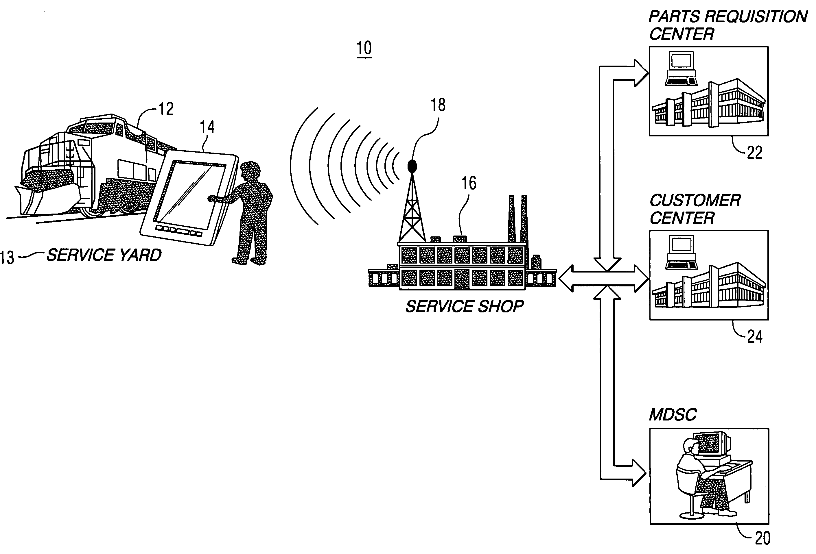
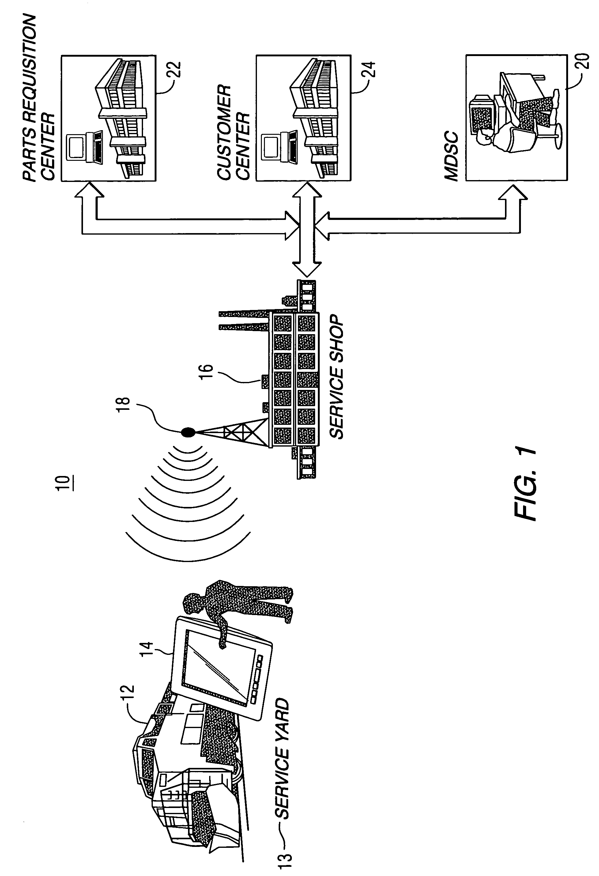
[0025]FIG. 1 is a schematic representation of an exemplary system that may benefit from the techniques of the present invention. Although illustrated and described ...


PUM


Abstract

Computerized method and system for graphically identifying replacement parts for selected equipment and a selected system thereof is provided. The method allows to provide a database comprising detailed parts data about the replacement parts for each assembly of the selected equipment, with the detailed data identifying each part in a selected assembly by providing a series of linked schematic representations of the selected assembly and any subassemblies thereof and respective parts. The method further allows to provide a respective identifier for uniquely identifying the selected equipment. An input/output device for communicating with the database is provided. The method allows to access the database to interface with the detailed parts data, and retrieve from the database detailed data about the selected equipment using the respective identifier for the equipment, wherein service personnel graphically progresses from the selected assembly to any relevant subassembly and replacement parts by following any appropriate links.

Description

[0001]This application claims the benefit of U.S. Patent Application Ser. No. 60 / 198,562 filed Apr. 20, 2000 and Ser. No. 60 / 258,747 filed Dec. 29, 2000.BACKGROUND OF THE INVENTION[0002]This invention relates to method and system for servicing generally complex equipment, and, more particularly, to computer-based method and system for graphically identifying replacement parts for servicing any selected equipment.[0003]The diagnosis, maintenance, and repair of generally complex equipment, such as mobile assets including on-road or off-road vehicles, ships, airplanes, railroad locomotives, trucks, and other forms of complex equipment including industrial equipment, consumer appliance equipment, medical imaging equipment, equipment used in industrial processes, telecommunications, aerospace applications, power generation, etc., involves extremely complex and time consuming processes. In the case of transportation equipment, efficient and cost-effective operation of a fleet of vehicles ...

Claims


Application Information

Patent Timeline
IPC IPC(8): G06F17/30B61K13/00B61L27/00G06F11/273G06Q30/00G07C5/00
CPCB61K13/00B61L27/0094G06F11/2294G06Q10/06G06Q30/02G06Q30/0623G06Q30/0633G06Q30/0643G07C5/008B61L27/57
Inventor COSTELLO, JAMES BRADYWILSON, CHRISTINESMATHERS, CLIFFORD E.PURI, ASHISHBADGER, BRIAN LEESTEMPKA, RAYMOND PAULVASH, KATHLEEN M.SMITH, JEFFERY M.LUBAK, MICHAEL ALLAN
Owner GENERAL ELECTRIC CO
Why Eureka
Try Eureka