Software debugger and software development support system for microcomputer operable to execute conditional execution instruction

a software development and microcomputer technology, applied in the direction of computing, error detection/correction, instruments, etc., can solve the problems of difficult to check the execution process, difficult to check the if, difficult to check the program logic described by the if-else control structure, etc., to achieve the effect of easy checking the execution process

Inactive Publication Date: 2007-09-04
PANASONIC CORP
View PDF23 Cites 19 Cited by
  • Summary
  • Abstract
  • Description
  • Claims
  • Application Information

AI Technical Summary

Benefits of technology

[0056]According to the above configuration, when producing a display at the time the program execution is caused to halt, if the address is within the live range of the condition flag, the execution state of the conditional execution instruction is checked, and the result can be presented to the user by changing display method so that the user can easily check the executing process of the program containing the conditional execution instruction.

Problems solved by technology

As a result, traditionally, it has been possible to check the program executing process by tracking the instructions as they are executed, but in the case of conditional execution instructions, there arises the problem that by just tracking the executed instructions only, it is difficult to check the executing process.
However, it is difficult to check if the processing “mul Ra, Ra, Rb” specified by the instruction at address 0x404 and the processing “mov Rc, Rb” specified by the instruction at address 0x408 have actually been executed.
The resulting problem is that it is difficult to check the program logic described by the if-else control structure.
The same problem occurs when displaying the results of a trace.

Method used


Image

  • Software debugger and software development support system for microcomputer operable to execute conditional execution instruction
  • Software debugger and software development support system for microcomputer operable to execute conditional execution instruction
  • Software debugger and software development support system for microcomputer operable to execute conditional execution instruction

Examples


embodiment 1

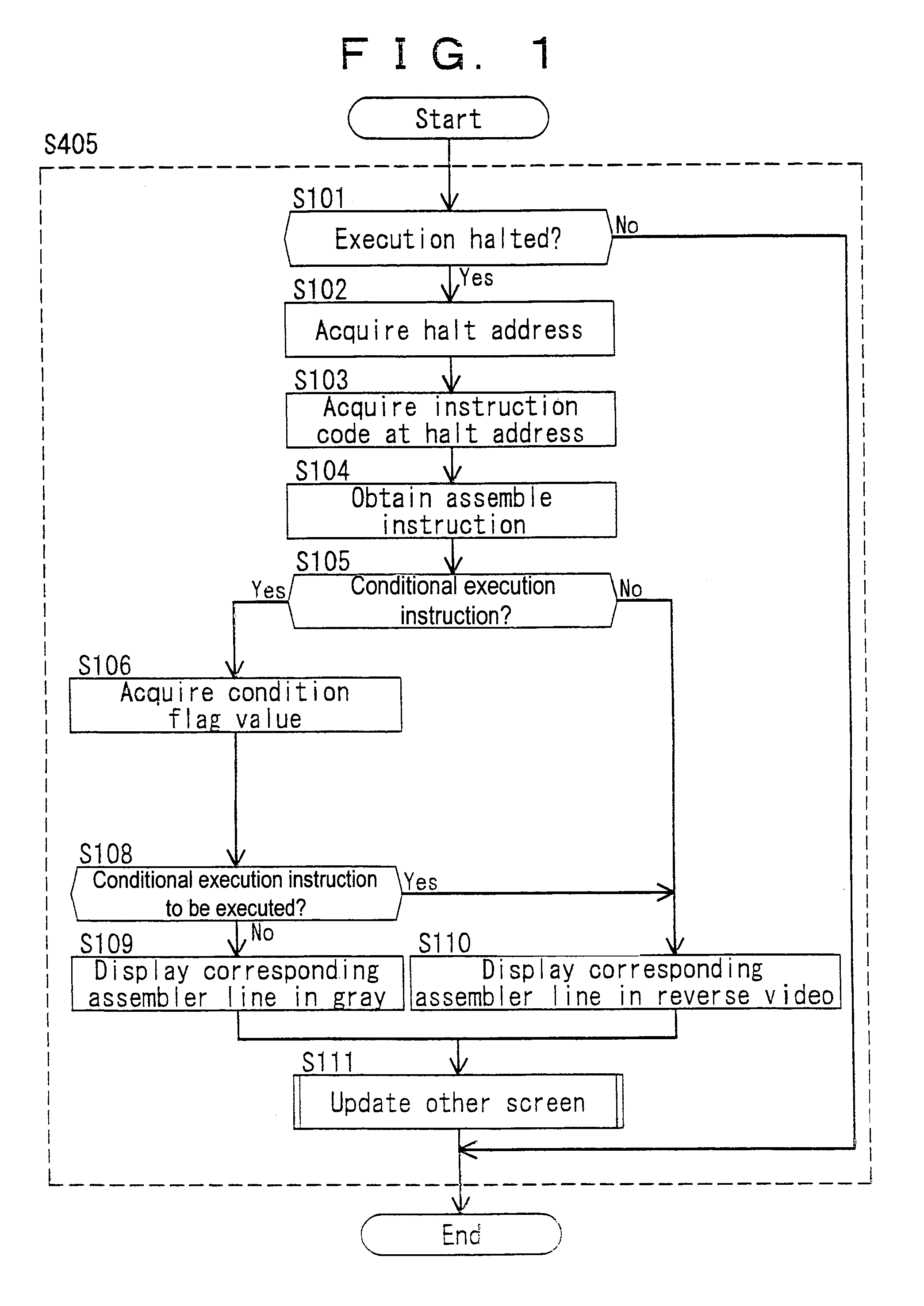
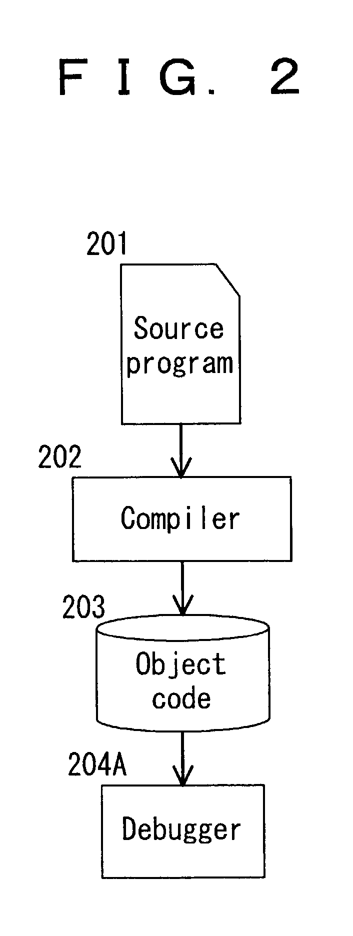
[0094]First, a first embodiment will be described below. FIG. 2 shows the configuration of a software development support system according to the first embodiment of the present invention. Reference numeral 201 is a C source program, using which a software developer as the user implements an application system being developed. Reference numeral 202 is a compiler, which takes the C source program 201 as an input, and outputs an object file 203 containing debugging information and microcomputer executable code used in the application system being developed. Reference numeral 204A is a debugger, which takes the object file 203 as an input, accepts commands from the software developer through a user interface, and performs debugging by checking the operation of the program being debugged.

[0095]The operation of the debugger 204A of this embodiment will be described below. FIG. 3 shows a functional block diagram of the debugger 204A.

[0096]Reference numeral 301 is a debugger processing sec...

embodiment 2

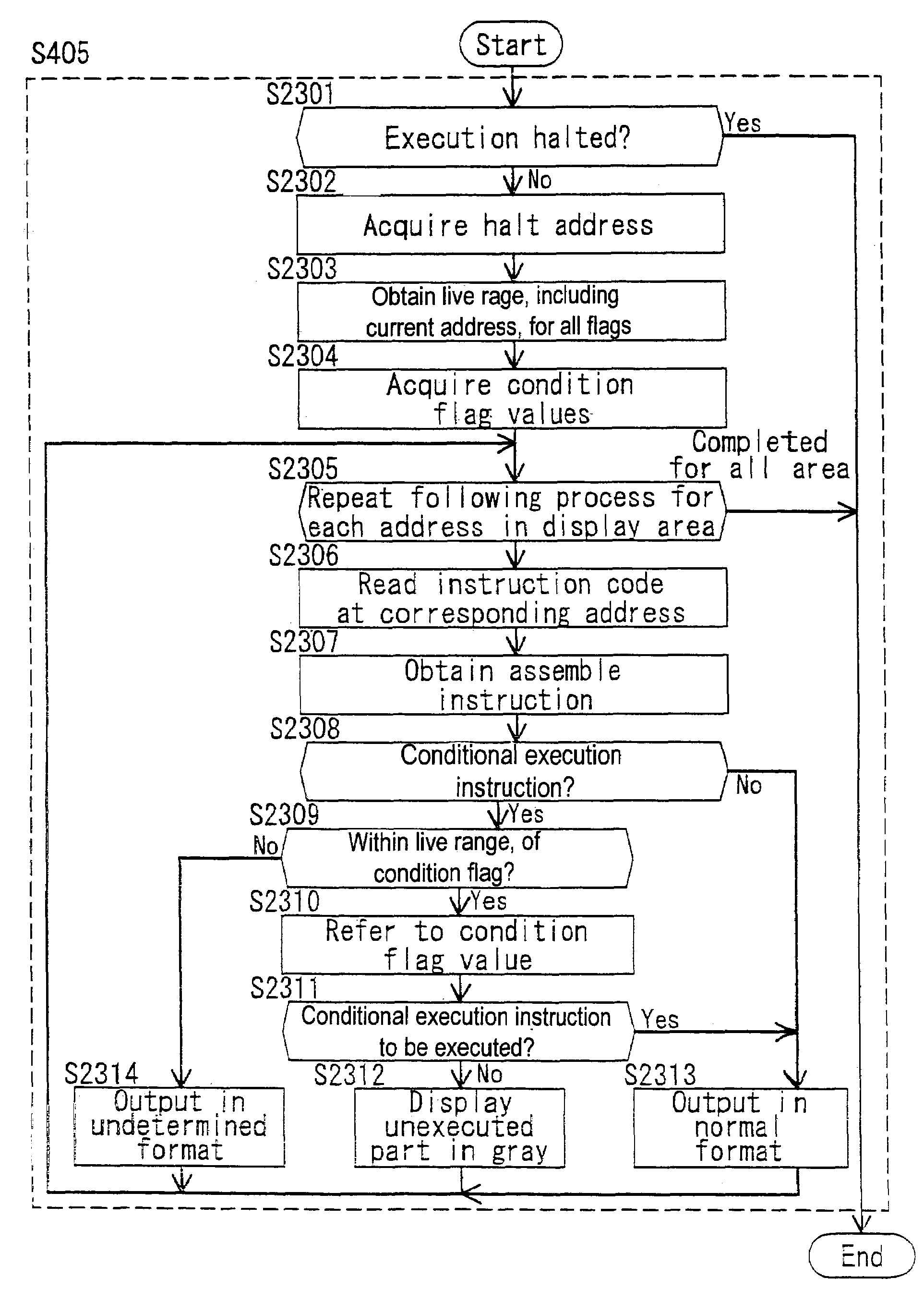
[0144]Next, a second embodiment of the present invention will be described. FIG. 8 is a diagram showing the configuration of a software development support system according to the second embodiment, and FIG. 9 is a functional block diagram of a debugger 204B; as can be seen, the configuration is substantially the same as that of the first embodiment. The second embodiment differs from the first embodiment in the process performed in the debugger 204B, and more specifically, in the trace data output process performed in the execution target environment 302 and the trace data output processing process in step S404.

[0145]In the second embodiment of the present invention, it is assumed that the execution target environment 302 is implemented as a software simulator of the target microcomputer.

[0146]FIG. 10 is a process flow diagram of the debugger processing section 301, the process flow being the same as that of the first embodiment of the present invention.

[0147]When a program execute...

embodiment 3

[0182]Next, a third embodiment of the present invention will be described.

[0183]FIG. 16 is a diagram showing the configuration of a software development support system according to the third embodiment; as can be seen, the configuration is substantially the same as that of the first embodiment. The difference from the first embodiment lies in the processing performed in the compiler 202C and debugger 204C.

[0184]FIG. 17 shows a functional block diagram of the compiler 202C according to this embodiment. In FIG. 17, reference numeral 1701 is a source program input section to which the source program is input.

[0185]Reference numeral 1702 is a program conversion section which converts the source program into an intermediate description level expression.

[0186]Reference numeral 1703 is a program optimizing section, which generates executable code by optimizing the program, for example, by rearranging the execution order of the operations in the intermediate description level program, and d...


PUM


Abstract

A software debugger tangibly embodied on a computer readable medium may display a microcomputer program being debugged so that a halt address at which the execution of the program is caused to halt can be distinguished from other addresses. When performing step-by-step execution of the program, a determination is made whether an instruction at the halt address is a predicate execution instruction or not. If the instruction is a predicate execution instruction, a condition flag value for the instruction is acquired. Based on the condition flag value, a determination is made whether the predicate execution instruction is to be executed or not. Then, the instruction at the halt address is displayed on a screen by changing a display method according to the result of the determination.

Description

BACKGROUND OF THE INVENTION[0001]1. Field of the Invention[0002]The present invention relates to a software debugger for debugging a program to be executed on a microcomputer, and a software development support system using the same; more particularly, the invention relates to a method of displaying the executing process of a microcomputer program having conditional execution instructions.[0003]2. Description of the Related Art[0004]With recent advances in electronic technology, increasing numbers of consumer appliances such as household electrical appliances have come to be equipped with built-in microcomputers, and the development of appliances entailing program development has become widespread.[0005]Furthermore, with increasing functionality of household electrical appliances, high performance microcomputers having conditional execution instructions for faster program execution have come to be used.[0006]In the development of a program, the program developer debugs the program b...

Claims


Application Information

Patent Timeline
Patent Type & Authority Patents(United States)
IPC IPC(8): G06F9/44G06F11/28G06F9/45G06F11/36
CPCG06F11/3636G06F11/3664
Inventor TSUBATA, SHINTAROSUMIDA, KIYOHIKO
Owner PANASONIC CORP
Why Eureka
Try Eureka