Method and instrument for measuring surface tension

a surface tension and measurement method technology, applied in the direction of measuring devices, scientific instruments, instruments, etc., can solve the problems of long time period, inability to continuously measure surface tension in a dynamic and accurate way, and inability to obtain a response, so as to achieve the effect of high operation security

Inactive Publication Date: 2007-09-11
JENSER TECH
View PDF10 Cites 10 Cited by
  • Summary
  • Abstract
  • Description
  • Claims
  • Application Information

AI Technical Summary

Benefits of technology

[0022]Since the fluid/gas is contained in a closed space the pressure of the slowly flowing liquid, caused by a constant liquid column, will give a constant suction height or a constant feeding of the liquid, to be counteracted by the combined action of the pressure of the fluid/gas and the tension in the surface at the border between the fluid/gas and the liquid and the resistance to the flow of the liquid that is caused by the viscosity of the liquid.
[0023]By differentially measuring the pressure between the liquid in the drop and an enclosed fluid a higher security of operation is achieved than in the previously known methods and measurement instruments. The temperature difference between the drop and the surrounding fluid is smaller resulting in a smaller precipitation of salts dissolved in the liquid. The risk that a liquid capillary will be clogged

Problems solved by technology

A problem existing today is that it is not possible to continuously measure surface tension in a dynamic and accurate way.
These methods result in a long time period before a response can be obtained.
Of course, the drawbacks of such methods are plural, including the following ones:Used time: Due to the fact that the measurement can not be made in the process it takes a longer time.No possibility of immediately obtaining a response.
Today manual work is required wh

Method used


Image

  • Method and instrument for measuring surface tension
  • Method and instrument for measuring surface tension
  • Method and instrument for measuring surface tension

Examples


Embodiment Construction

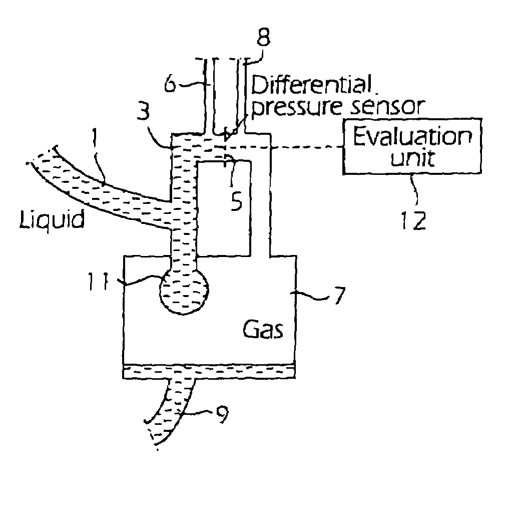
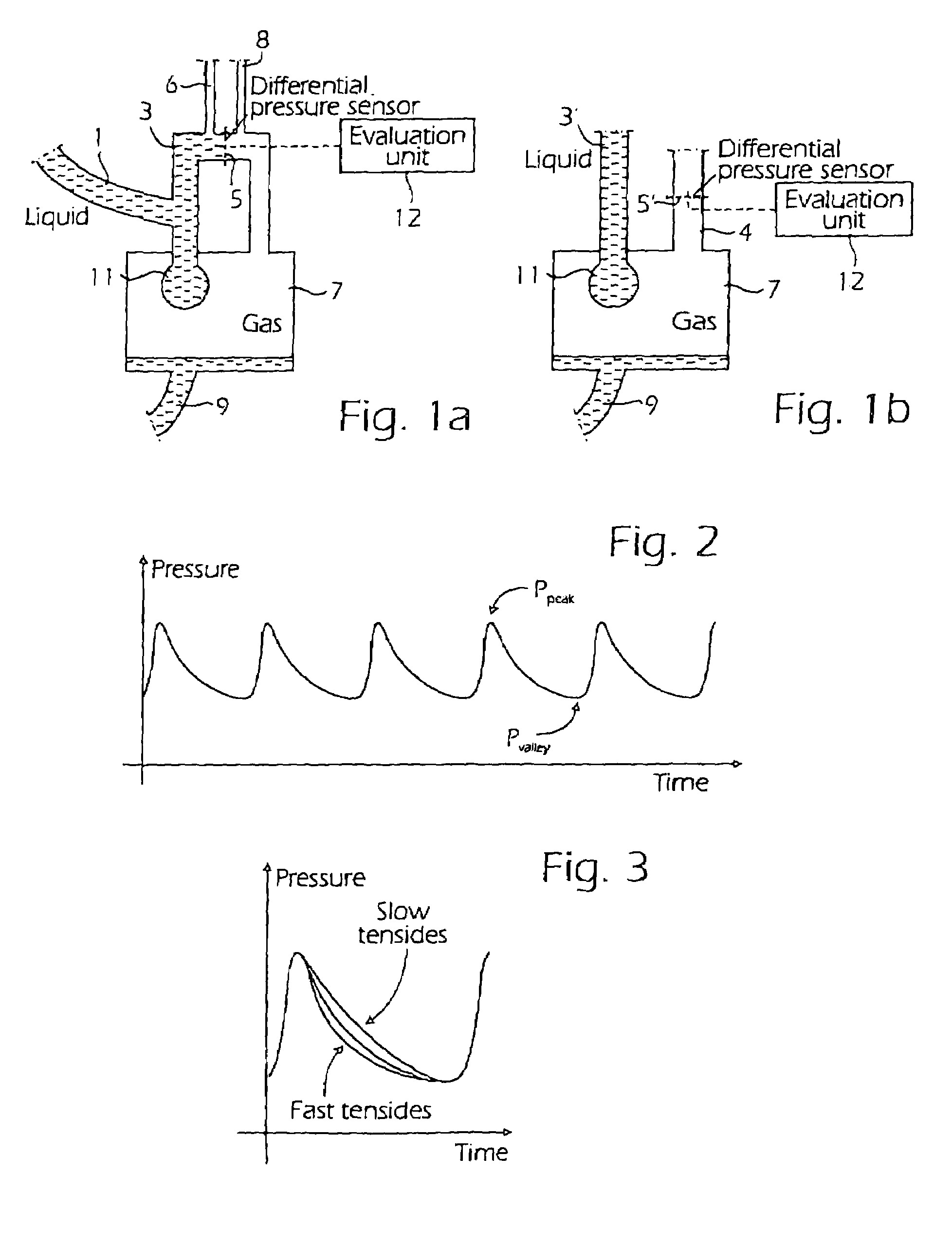
[0033]In FIG. 1a the central parts of an installation for detection or measurement of surface tension, dynamically and statically, between a liquid and a gas using differential pressure measurement are shown, or generally between a first liquid having a higher, generally a significantly higher, density and a second fluid that has a lower density and can be a gas or a liquid. The liquid the surface tension of which is to be measured is fed using a substantially constant pressure from a source, not shown in this figure, through an intake pipe 1 to a side inlet in one of the for example vertically located legs of a capillary having an inverted U-shape. At the highest point of the U-shape, in its web portion, the capillary 3 is divided by a flexible diaphragm, the deflection of which can be measured using some device, not shown, coupled to the diaphragm. The measurement can be performed for example by detecting changed resistance or capacitance of suitably arranged electrically conducti...


PUM


Abstract

For measuring the surface tension between a liquid and fluid such as a gas, a capillary (3, 3′) is used in which the liquid slowly flows and at the end of which drops (11) are formed, falling off into a closed space (7) containing the fluid. Using a pressure sensor (5, 5′) the pressure is measured which can be the absolute pressure of a fluid volume enclosed in the closed space or alternatively a differential pressure measured as the pressure difference between the liquid in the capillary and fluid contained in the closed space. The pressure is measured when one or more drops are formed and full off. The obtained pressure curves are evaluated electronically (12) and provide a value of the surface tension. The measurement can be made within a fairly short time with a high operational reliability. The temperature difference between the drop and the surrounding fluid is small resulting in a little precipitation of salts dissolved in the liquid, reducing the risk that the liquid capillary with be blocked. A pump can be connected (9) to the closed space to create a subatmospheric pressure therein and thereby assist in restarting the liquid flow through the capillary if it would be blocked. The velocity of the liquid flow to the drop can be controlled using the pump.

Description

[0001]This application is the US national phase of international application PCT / SE02 / 01446, filed in English on 09 Aug. 2002, which designated the US. PCT / SE02 / 01446 claims priority to SE Application No. 0102701-0 filed 10 Aug. 2001 and SE Application No. 0200954-6 filed 27 Mar. 2002. The entire contents of these applications are incorporated herein by reference.RELATED APPLICATIONS[0002]This application claims priority and benefit from from Swedish patent application No. 0102701-0, filed 10 Aug. 2001, and Swedish patent application No. 0200954-6, filed 27 Mar. 2002, the entire teachings of which are incorporated herein by reference.TECHNICAL FIELD[0003]The present invention relates to a method and an instrument for measuring surface tension by measuring pressures, for example by differential pressure measurement between a liquid and a gas.BACKGROUND[0004]For many different processes it is of great importance to know the magnitude of the surface tension of a liquid. The surface ten...

Claims


Application Information

Patent Timeline
IPC IPC(8): G01N13/00G01N13/02
CPCG01N13/02G01N2013/0241
Inventor SKOGO, MARTENELVESJO, JOHN
Owner JENSER TECH
Why Eureka
Try Eureka