
Variable compression ratio scheduling at idle speed conditions

a compression ratio and idle speed technology, applied in the direction of engine cooling apparatus, control device of cooling apparatus, electric control, etc., can solve the problems of limited compression ratio and engine knocking at idle, and achieve the effect of reducing compression ratio, high thermal efficiency, and high compression ratio

Active Publication Date: 2007-09-11
FORD GLOBAL TECH LLC
View PDF5 Cites 13 Cited by
  • Summary
  • Abstract
  • Description
  • Claims
  • Application Information

AI Technical Summary

Benefits of technology

The invention relates to a method for selecting the compression ratio of an idling internal combustion engine based on various factors such as engine torque demand, temperature, and accessory loads. The method uses a normalized airflow parameter that is determined based on air charge temperature and engine coolant temperature to select the appropriate compression ratio. This helps to prevent engine knock and maximize fuel efficiency. The method also takes into account the idle speed of the engine, which is computed based on the selected compression ratio and other factors such as catalyst temperature and engine coolant temperature. The invention ensures smooth engine operation during transitions and avoids engine knock.

Problems solved by technology

In spark-ignition engines, compression ratios are limited by engine knock or autoignition which tends to occur at lower engine speeds and higher engine torques.
However, if the other factors leading to knock, such as low humidity, high ambient temperature, low octane fuel, etc. occur, the engine can knock at idle.

Method used


Image

  • Variable compression ratio scheduling at idle speed conditions
  • Variable compression ratio scheduling at idle speed conditions
  • Variable compression ratio scheduling at idle speed conditions

Examples


Embodiment Construction

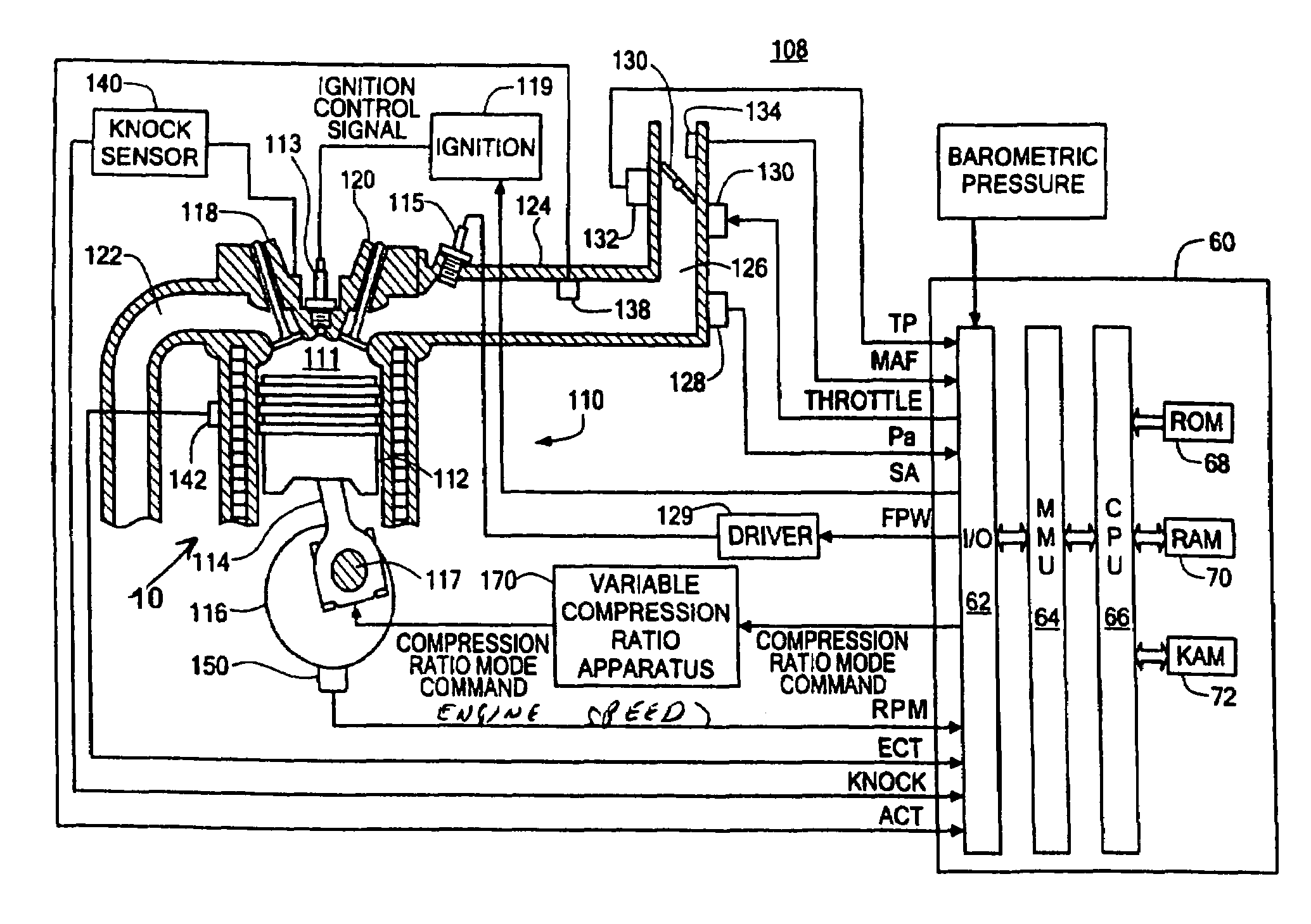
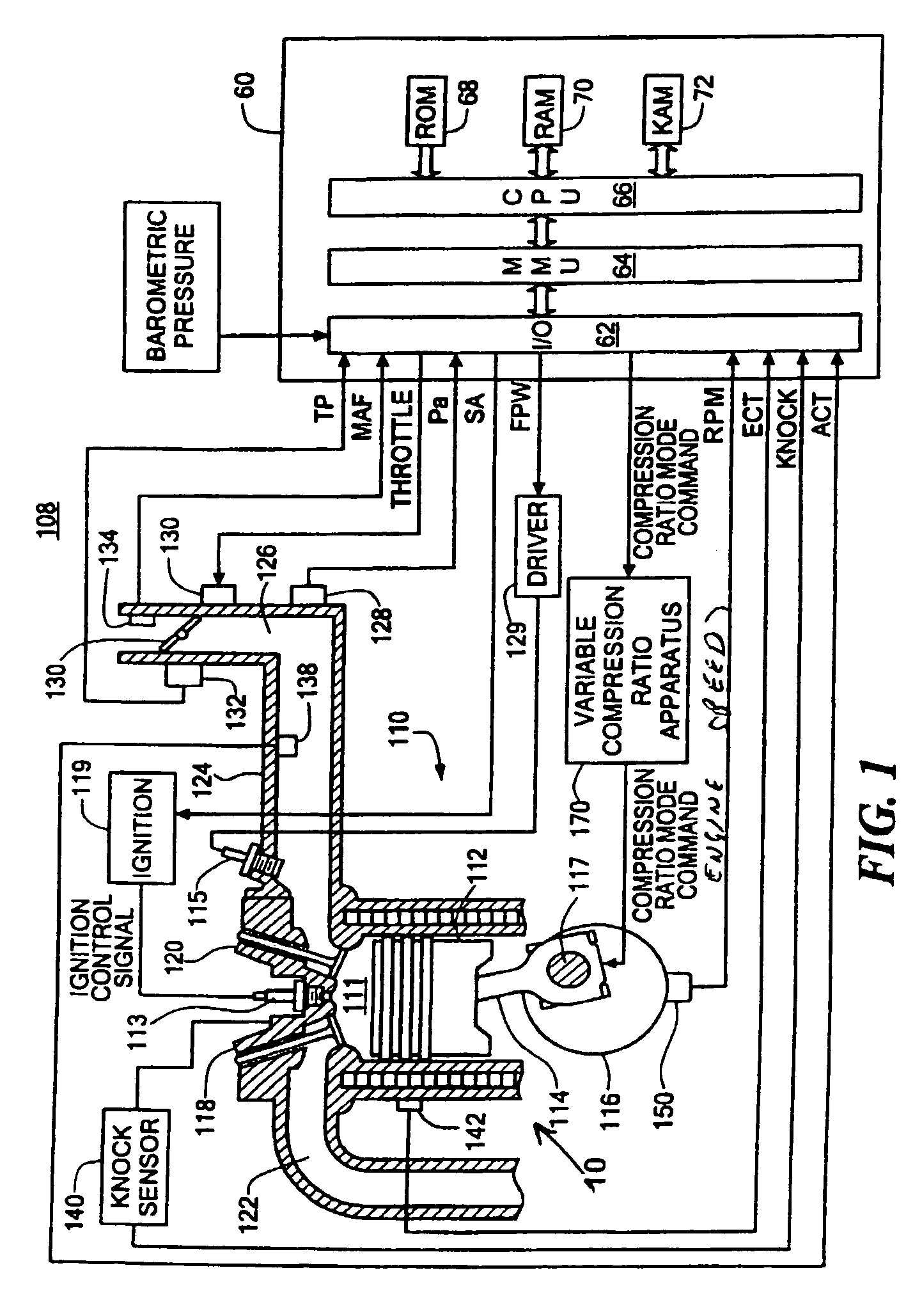
[0016]FIG. 1 shows an exemplary variable compression ratio internal combustion engine 10 in accordance with the present invention. As will be appreciated by those of ordinary skill in the art, the present invention is independent of the particular underlying engine configuration and component designs, and as such can be used with a variety of different internal combustion engines having more than one compression ratio operating modes. The engine for example can be constructed and arranged as a discrete compression ratio engine operating for example at a high compression or at low compression, or as a continuously variable compression ratio engine capable of operating at an infinite number of discrete compression ratios. Similarly, the present invention is not limited to any particular type of apparatus or method required for varying the compression ratio of the internal combustion engine.

[0017]Referring again to FIG. 1, the engine 110 includes a plurality of cylinders (only one show...


PUM


Abstract

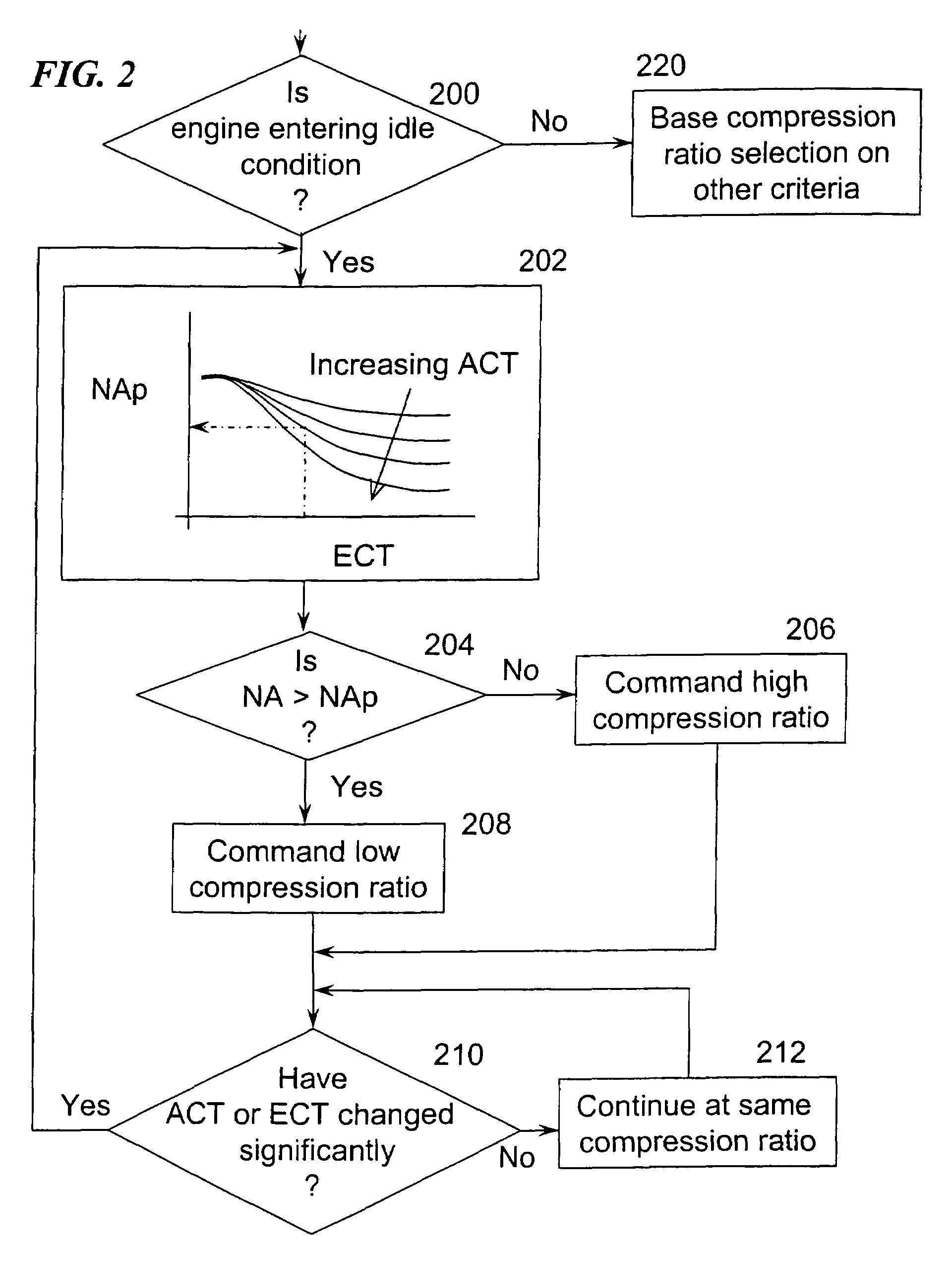
A method for selecting compression ratio of a variable compression ratio internal combustion engine when such engine is operating under an idle condition is disclosed. The compression ratio is selected to avoid engine knock, an undesirable phenomenon which is more likely at higher temperatures, higher compression ratios, lower engine speeds, and higher engine torques. The selected compression ratio is based on one or more of engine torque required to drive engine accessories, engine coolant temperature, engine air temperature, and transmission status (neutral idle or drive idle). A normalized airflow parameter is computed or found in a lookup table based on engine coolant temperature and engine air temperature. When actual normalized airflow (that which provides necessary engine torque to drive engine accessories and overcome engine friction) exceeds normalized airflow parameter exceeds, a higher compression ratio is selected.

Description

TECHNICAL FIELD[0001]This invention relates generally to internal combustion engines having variable compression ratios and more particularly to methods for scheduling the compression ratio for reciprocating, internal combustion engines.BACKGROUND AND SUMMARY[0002]As is known in the art, the compression ratio of an internal combustion engine is defined as the ratio of the cylinder volume when the piston is at bottom-dead-center (BDC) to the cylinder volume when the piston is at top-dead-center (TDC)—generally, the higher the compression ratio, the higher the thermal efficiency and fuel economy of the internal combustion engine. In spark-ignition engines, compression ratios are limited by engine knock or autoignition which tends to occur at lower engine speeds and higher engine torques. Engine knock does not typically occur at engine idle, which is a low speed, low torque condition. However, if the other factors leading to knock, such as low humidity, high ambient temperature, low oc...

Claims


Application Information

Patent Timeline
Patent Type & Authority Patents(United States)
IPC IPC(8): F02B75/04
CPCF02B75/04F02B75/045F02D41/08F01P2025/31F01P2037/02
Inventor GLUGLA, CHRISTOPHER
Owner FORD GLOBAL TECH LLC
Learn More