
Apparatus for measuring specific absorption rate of radio communication apparatus

a radio communication apparatus and specific absorption technology, applied in the construction details of electrical devices, transmission monitoring, instruments, etc., can solve the problems of affecting the influence of electromagnetic waves radiated from a portable radio communication apparatus onto the human body, affecting the accuracy of sar measurement, and disadvantageously impossible to check the sar of the mobile phone on the production line by the conventional sar measuring apparatus or method. achieve the effect of higher precision

Active Publication Date: 2007-09-11
PANASONIC INTELLECTUAL PROPERTY CORP OF AMERICA
View PDF14 Cites 24 Cited by
  • Summary
  • Abstract
  • Description
  • Claims
  • Application Information

AI Technical Summary

Benefits of technology

[0011]It is an object of the present invention to provide an SAR measuring apparatus capable of solving the above-mentioned conventional disadvantages, and capable of measuring an SAR of a radio communication apparatus by a simpler method, with higher precision, with a simpler configuration, as compared with the prior art.
[0022]Accordingly, according to the SAR measuring apparatus and method of the present invention, the near magnetic field distribution and the SAR distribution are measured using as the reference antenna the minute array antenna including a plurality of minute antennas or a flat-plane-shaped dipole antenna, and then the magnetic field distribution in free space of the portable radio communication apparatus is measured. It is thereby possible to estimate the SAR distribution by quite a simpler method with higher precision, as compared with the prior art.

Problems solved by technology

Accompanying this, a problem regarding the influence of electromagnetic waves radiated from a portable radio communication apparatus onto a human body has been caused.
For this reason, it takes a considerably long time to measure the SAR.
It is, therefore, disadvantageously impossible to check the SAR of the mobile phone on the production line by the conventional SAR measuring apparatus or method.
For this reason, an actual surface magnetic field cannot be measured, and an error is generated in the measured SAR.
In addition, when the portable radio communication apparatus, an ordinary dipole antenna, or the like is employed as a reference antenna, a part having a low magnetic field intensity locally may be caused, and magnetic field detection precision is deteriorated.
As a result, an SAR estimation error is disadvantageously generated.

Method used


Image

  • Apparatus for measuring specific absorption rate of radio communication apparatus
  • Apparatus for measuring specific absorption rate of radio communication apparatus
  • Apparatus for measuring specific absorption rate of radio communication apparatus

Examples


first preferred embodiment

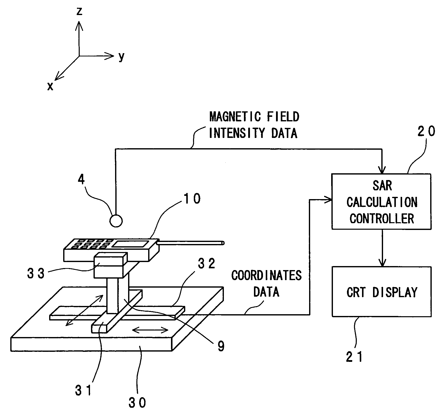
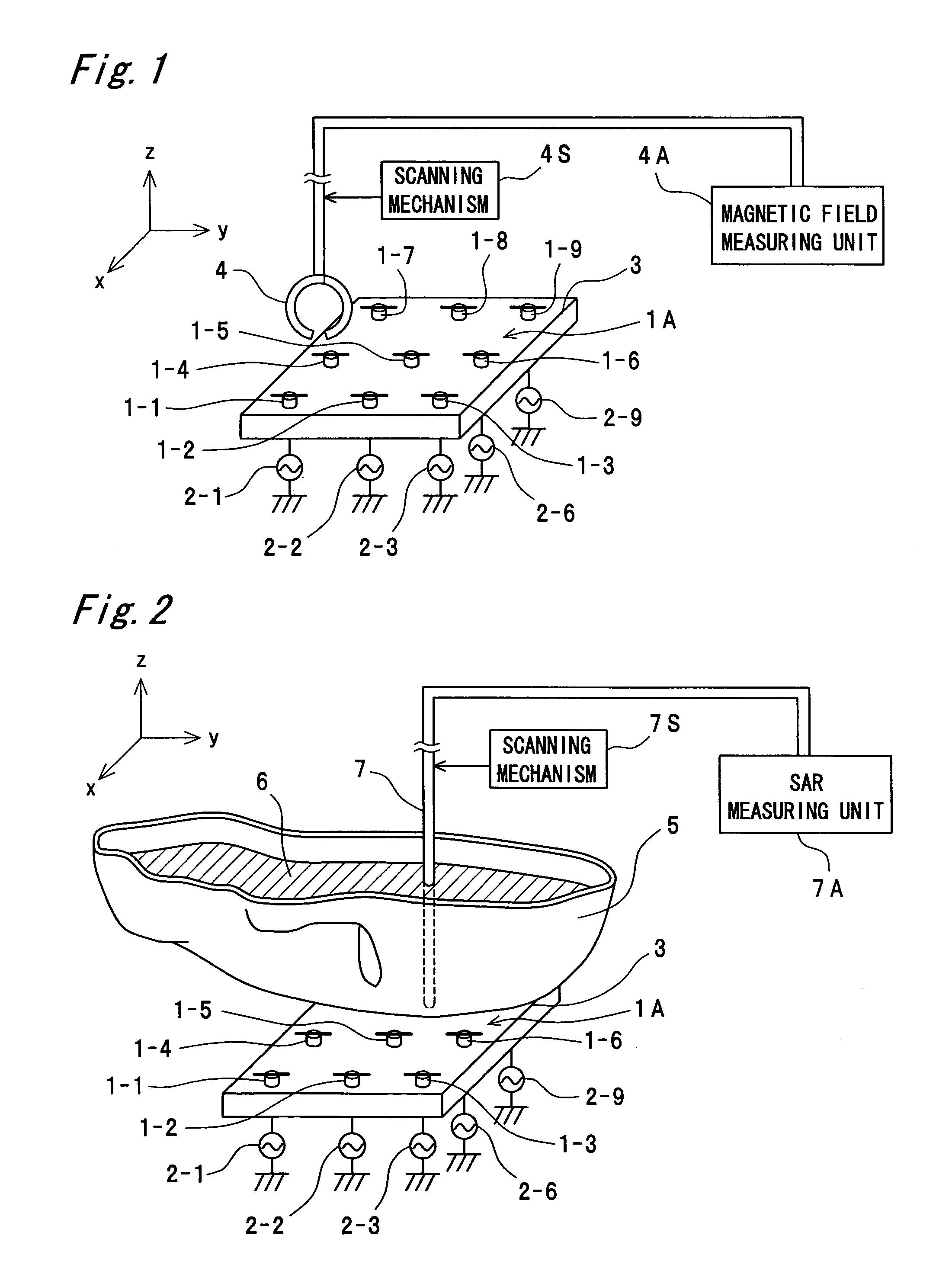
[0045]FIG. 1 is a perspective view and a block diagram which illustrate a magnetic field measuring apparatus of an SAR measurement system according to a first preferred embodiment of the present invention. FIG. 2 is a perspective view and a block diagram which illustrate an SAR measuring apparatus of the SAR measurement system according to the first preferred embodiment of the present invention. Further, FIG. 12 is a perspective view and a block diagram which illustrate a configuration of the SAR measurement system according to the preferred embodiment of the present invention. FIG. 13 is a flow chart which illustrates an SAR distribution calculation processing executed by an SAR calculation controller 20 shown in FIG. 12.

[0046]An SAR distribution calculation method according to the preferred embodiment of the present invention is characterized by executing an SAR distribution calculation processing shown in FIG. 13 using a minute dipole array antenna 1A including nine minute dipole...

second preferred embodiment

[0102]FIG. 18 is a plan view which illustrates a flat-plane-shaped dipole antenna apparatus 16 according to a second preferred embodiment of the present invention. FIG. 19 is a circuit diagram which illustrates a feeder circuit for feeding electric power to the flat-plane-shaped dipole antenna apparatus 16 shown in FIG. 18. The second preferred embodiment is characterized by measuring the SAR distribution using the flat-plane-shaped dipole antenna apparatus 16 instead of the minute dipole array antenna 1A according to the first preferred embodiment.

[0103]The flat-plane-shaped dipole antenna apparatus 16 is made of, for example, a copper plate having a thickness of 0.5 mm. In a manner similar to that of the first preferred embodiment, the second preferred embodiment is intended to be able to form a uniform magnetic field distribution or a substantially magnetic field distribution within a measurement range of the portable radio communication apparatus. In order to widen the range of ...


PUM


Abstract

In an apparatus for measuring a specific absorption rate (SAR), a first near magnetic field distribution of a radio wave radiated from an array antenna of a reference antenna including a plurality of minute antennas is measured, and an SAR distribution with respect to the radio wave radiated from the array antenna is measured with a predetermined phantom. Then a distribution of a transformation coefficient α is calculated by dividing the measured SAR distribution by a square of the measured first near magnetic field distribution, a second near magnetic field distribution of a radio wave radiated from a measured radio communication apparatus is measured, and an SAR distribution with respect to the radio wave radiated from the radio communication apparatus is calculated by multiplying a square of the measured second near magnetic field distribution by the calculated distribution of the transformation coefficient α.

Description

BACKGROUND OF THE INVENTION[0001]1. Field of the Invention[0002]The present invention relates to an apparatus for measuring a specific absorption rate (hereinafter, referred to as an “SAR”), and in particular, to an apparatus for measuring an SAR of a radio communication apparatus such as a mobile phone, a portable radio communication apparatus, or the like.[0003]2. Description of the Related Art[0004]Recently, portable radio communication apparatuses such as a mobile phone have spread greatly. Accompanying this, a problem regarding the influence of electromagnetic waves radiated from a portable radio communication apparatus onto a human body has been caused. As a general index of the influence, an SAR is provided. The SAR is an electric power absorbed by a unit mass by exposing a living body such as a human body or the like to an electromagnetic field, and is expressed by the following Equation (1):SAR=(σE2) / ρ  (1),[0005]where E [V / m] is an electric field intensity, σ[S / m] is an el...

Claims


Application Information

Patent Timeline
Patent Type & Authority Patents(United States)
IPC IPC(8): G01R29/08H01Q17/00
CPCG01R29/0857G01R29/0878
Inventor OZAKI, AKIHIROOGAWA, KOICHIKOYANAGI, YOSHIOSAITO, YUTAKAKAJIWARA, SHOICHIASAYAMA, YOSHITAKAYAMAMOTO, ATSUSHI
Owner PANASONIC INTELLECTUAL PROPERTY CORP OF AMERICA
Learn More