Light scattering detector

a detector and light scattering technology, applied in the field of sample analysis, can solve the problems of large size of analyte signal, limited light source power in commercial lsd sections, and degree of scattering, and achieve the effect of efficient direct light scattering and increased light collection

Inactive Publication Date: 2007-09-11
UNIVERSITY OF MISSOURI
View PDF59 Cites 19 Cited by
  • Summary
  • Abstract
  • Description
  • Claims
  • Application Information

AI Technical Summary

Benefits of technology

[0008]An exemplary embodiment of the invention includes features for high sensitivity evaporative light scattering detection. The exemplary embodiment includes a detection cell to accept particles suspended in a gas stream and permit a polarized light beam to pass through a trajectory of the particles and gas stream. A light source produces the polarized beam. A sample light detector is disposed to detect light scattered in the detection cell. A light trap accepts the polarized beam after it passes through the detection cell. The light trap includes an elongated housing through which the polarized beam passes, and light absorbing material within the elongated housing. An absorptive absorptive filter properly aligned with the polarization direction of the beam is disposed to intersect the polarized beam. Additionally, a reference light detector may detect light passing the absorptive filter and provide a reference signal that may be used for noise cancellation.
[0009]Other embodiments of the invention provide increased light collection. An example embodiment uses a compound lens to efficiently direct light scattered from a light beam toward a sample detector and a spherical mirror to direct light toward the compound lens. Embodiments of the invention include temperature-controlled entrance and exit ports that control particle trajectory. Embodiments of the invention include a reference cell disposed between a detection cell and a light trap, and the reference cell includes lenses and a spherical mirror to direct light toward a reference light detector. The reference light detector provides a reference signal that may be used for noise cancellation. In another embodiment, a reference signal is provided by a reference light detector that detects light passing through an absorptive filter in the light trap.

Problems solved by technology

More powerful light sources and more efficient light collection optics can increase the size of the analyte signal, but the light source power is limited in commercial LSD sections because scattering from sources other than analyte particles quickly swamps the detector signal as the light source power is raised past relatively low light levels.
However, some degree of scattering also occurs during each reflection.
Well-defined, e.g., collimated, light beams help reduce troublesome spurious scattering by detector cell components and the light trap at increased light source powers, but such beams may be difficult to realize with incandescent light sources.
This large background of scattered light results in a large, inconvenient DC baseline offset.
The large background is also a source of noise and at high enough levels, it will saturate the detector.

Method used


Image

  • Light scattering detector
  • Light scattering detector
  • Light scattering detector

Examples


Embodiment Construction

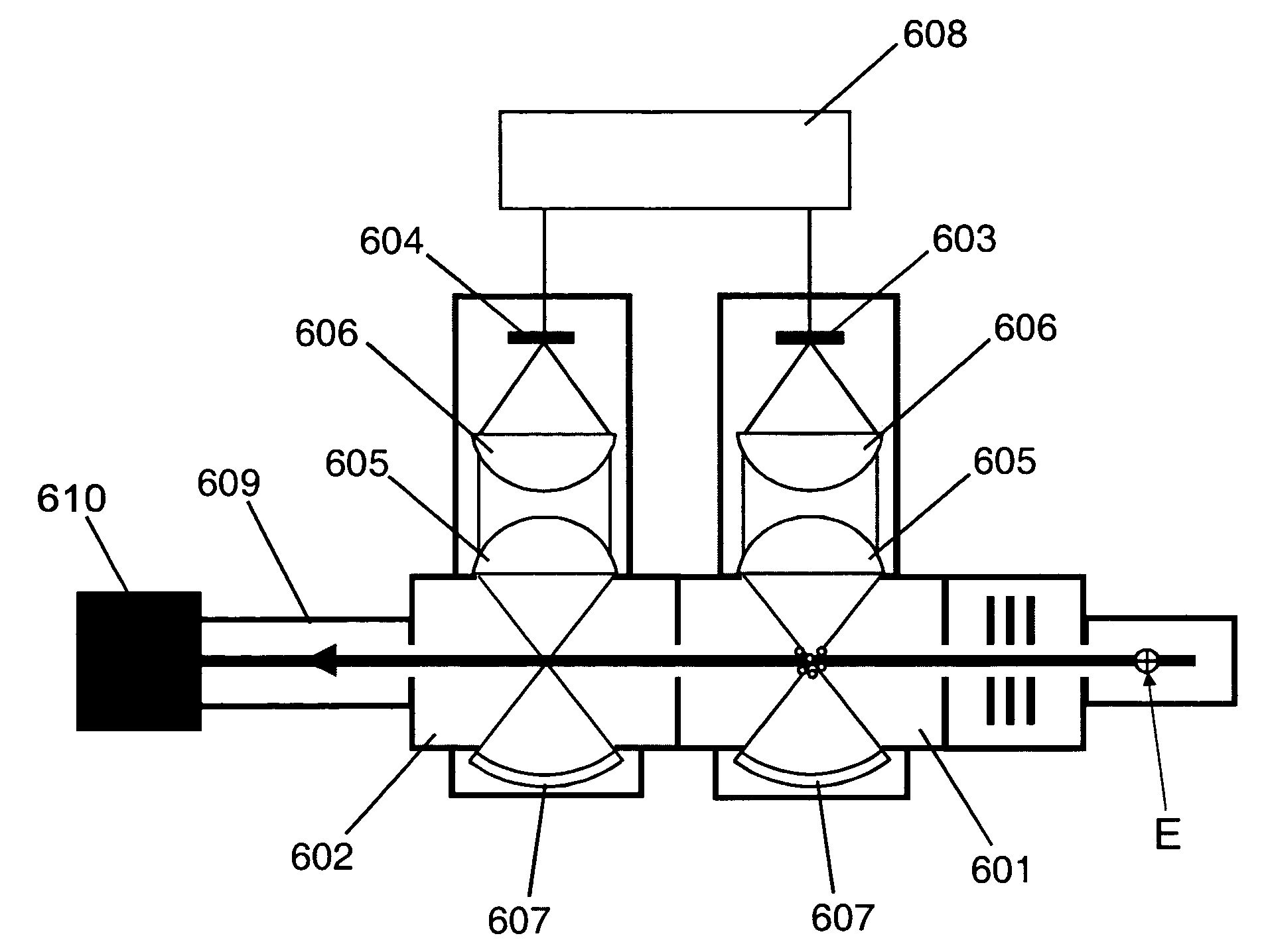
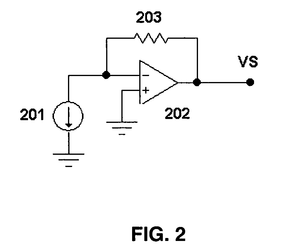
[0019]The invention is directed to high sensitivity light scattering detection methods, devices and systems. Through various aspects of the invention, especially when applied in combination, scattering from background sources is made very low. A light scattering detector device of the invention accordingly has high sensitivity and exhibits a low limit of detection. A light scattering detector device of the invention may be an independent device, or it may form a section / component of another device, such as an evaporative light scattering detector device. Embodiments of the invention also obtain a reference signal from a through-beam portion (portion that is not scattered) of the light source that is detected at the backside of an absorptive filter at the end of a light trap. The reference signal is used in a detection circuit to cancel background effects, increase the sensitivity and lower the limit of detection.

[0020]In accordance with embodiments of the invention, a detection cell...


PUM

PropertyMeasurementUnit
poweraaaaaaaaaa
frequencyaaaaaaaaaa
powersaaaaaaaaaa

Abstract

The invention concerns high sensitivity light scattering detection and its application to evaporative light scattering detection in liquid chromatography. The exemplary embodiment includes a detection cell to accept particles suspended in a gas stream and permit a polarized light beam to pass through a trajectory of the particles and gas stream. A sample light detector is disposed to detect light scattered in the detection cell. A light trap accepts the polarized beam after it passes through the detection cell. The light trap includes an elongated housing through which the polarized beam passes, and light absorptive material within the elongated housing. An absorptive filter is aligned such that the angle of incidence of the light beam upon the filter approximates Brewster's angle and the electric field vector of the beam is aligned with the plane of incidence between the beam and the filter. Other embodiments of the invention provide increased light collection. Embodiments of the invention include temperature-controlled entrance and exit ports that control particle trajectory. Embodiments of the invention include a reference cell disposed between a detection cell and a light trap, and the reference cell includes lensing and a spherical mirror to direct light toward a reference light detector. The reference light detector provides a reference signal that may be used with noise cancellation circuitry, operating in either voltage or current mode, to reduce light source noise in the sample signal.

Description

FIELD OF THE INVENTION[0001]A field of the invention is sample analysis. A specific exemplary field of the invention is liquid chromatography.BACKGROUND[0002]Sample analysis is used to determine a property or properties of a sample. One type of analysis is an optical analysis. Optical properties of a sample can provide information about the sample. Optical sample analysis is often used for detection in liquid chromatography. Liquid chromatography is used to separate a sample liquid mixture into its individual components and to quantify each component in the sample.[0003]Evaporative light scattering detectors (ELSDs) are used for liquid chromatography analysis. In a typical liquid chromatography configuration, a solvent mixture (the mobile phase) containing dissolved solute (the analyte) flows continuously through a column and into an ELSD. Within the ELSD, liquid from the column is converted into small droplets by a nebulization process that uses a carrier gas, usually nitrogen. As ...

Claims


Application Information

Patent Timeline
Patent Type & Authority Patents(United States)
IPC IPC(8): G01N21/00G01N21/03G01N21/53G01N30/74G01N30/84
CPCG01N21/0303G01N30/74G01N21/53G01N2030/847G01N2030/8494G01N2201/0642G01N21/47
Inventor LARSEN, DAVID W.XU, ZHI
Owner UNIVERSITY OF MISSOURI
Why Eureka
Try Eureka