Method of controlling a power generation system

a power generation system and control system technology, applied in the direction of engines, machines/engines, mechanical equipment, etc., can solve the problems of inefficient plant performance, loss of revenues to the plant operator, and financial losses to the operator of the plant or its customers

Active Publication Date: 2007-09-18
SIEMENS ENERGY INC
View PDF17 Cites 54 Cited by
  • Summary
  • Abstract
  • Description
  • Claims
  • Application Information

AI Technical Summary

Benefits of technology

[0012]System 10 may include a water injection system 28 and an exemplary fuel system 30. Fuel system 30 may provide two separately controllable flows of combustible fuel to combustor 20. A main fuel flow 32 may be supplied to a pre-mixed combustion zone of combustor 20 and a pilot fuel flow 34 may be supplied to a pilot diffusion combustion zone of combustor 20. Another exemplary combustor 20 may include multiple internal fuel stages that are fueled at different locations by fuel system 30 to improve fuel-air mixing. For example, combustor 20 may include a pilot stage and A, B and C stages. The total fuel flowing into the combustor may be expressed as respective fuel fractions of these stages. These fuel fractions may be adjusted or tuned to improve combustor dynamics and emissions at a given load, ambient temperature and specific humidity.
[0017]One aspect of the invention provides a closed loop IGV control. The closed loop IGV control allows for modulating the IGVs iteratively from a selected starting point to obtain a desired setpoint at a given engine load condition based on a corrected exhaust or outlet temperature of turbine 24. This eliminates the biases associated with a predetermined IGV schedule based on a normalized load and ambient conditions such as temperature and specific humidity. The closed loop IGV control decreases the complexity in the control system and simplifies system commissioning and tuning. This is because the relatively complicated process of setting up the ambient temperature biasing and load biasing that would otherwise be used to improve the engine stability at different engine operating conditions is no longer required. Normalized load may be defined as the percentage load normalized to the maximum power of a turbine 24 at a particular ambient temperature. For example, turbine 24 may generate maximum power or baseload (100% load) of 215MW on a 0° F. ambient temperature day and of 150MW on a 110° F. ambient temperature day. A 60% normalized load for these temperatures would be 129MW (215×0.6) and 90MW (150×0.6), respectively.
[0018]Aspects of the invention allow the engine controllers to control the exhaust temperature based on a closed loop or computer controlled IGV schedule rather than a predetermined IGV schedule. The closed loop IGV schedule is determined in response to operating conditions of a turbine and / or based on such conditions. This increases the versatility of the overall engine control process by reducing the variation in firing temperature that may result from changes in ambient temperature. This minimizes the drift in NOx / CO emissions and combustor dynamics. Enabling a closed loop control on the IGVs based at least in part on engine exhaust temperature allows the IGVs to assume operating positions that are not preset positions. This eliminates any hysterisis issues caused by the mechanical linkage in an IGV actuator where engine opertion is dependent on accurate preset angles for the IGVs.
[0019]In one aspect the IGVs may automatically modulate to attain or maintain a corrected exhaust temperature. The engine exhaust temperature has a more direct correlation to the combustion flame or firing temperature compared to that of the IGV angle. The NOx and CO emissions may be controlled by modulating the flame temperature directly through controlling the exhaust temperature rather than indirectly by changing the postion of the IGVs. This is because changing IGV position will increase / decrease flame temperature with changes in ambient temperature at a constant load. This is due to variations in engine air mass flow rates caused by changes in ambient temperature. Aspects of the invention provide the capability to maintain either a constant actual flame temperature or constant actual exhaust temperature above approximately a 50% normalized load to 100% or baseload operation. This control on flame temperature reduces or eliminates the risk of over firing the engine and consequently improves hot parts life, prevents part load engine stalling and reduces the NOx / CO emissions drift.

Problems solved by technology

Failure to load and unload the engine efficiently may lead to financial losses to the operator of the plant or its customers.
Otherwise, delays may be experienced in achieving baseload operations causing unscheduled engine tuning operations and related maintenance procedures with a resulting loss of revenues to the plant operator.
This leads to inefficient plant performance that may cause higher levels of emissions than desired.

Method used


Image

  • Method of controlling a power generation system
  • Method of controlling a power generation system
  • Method of controlling a power generation system

Examples


Embodiment Construction

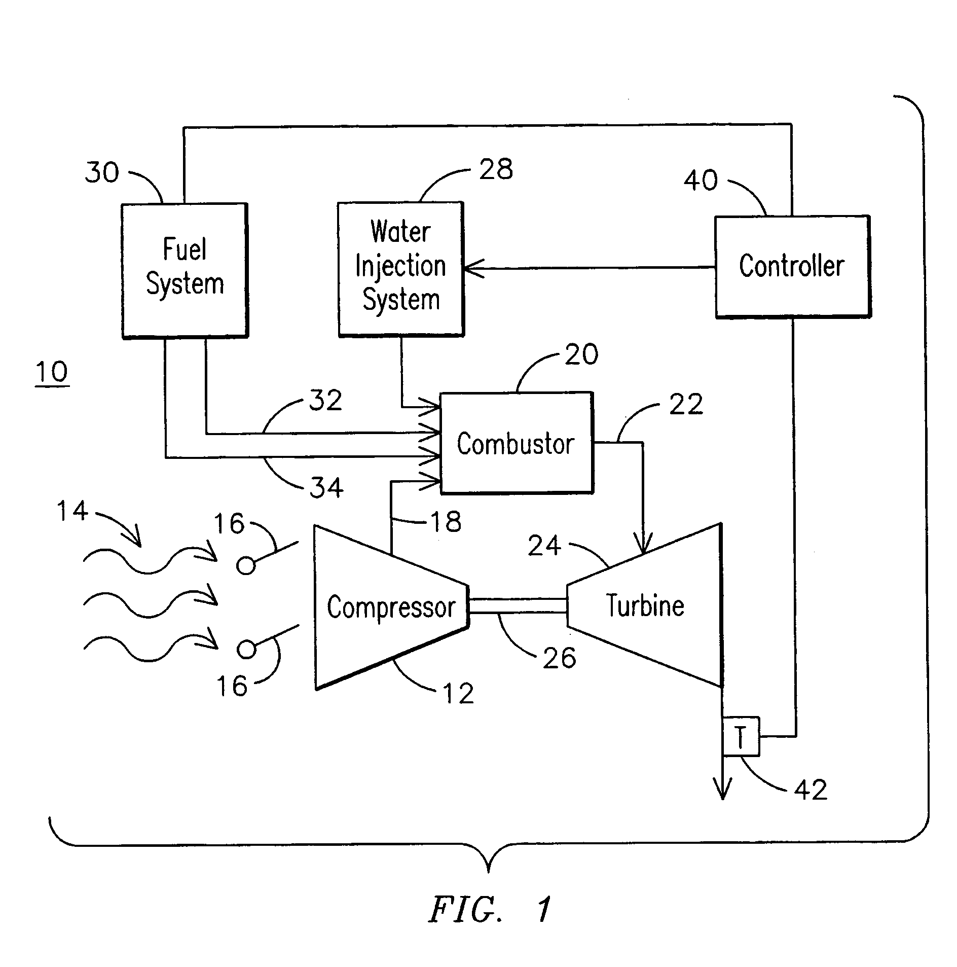
[0011]FIG. 1 illustrates a schematic of an exemplary gas turbine system 10, certain components of which may be referred to herein as an engine, which may employ embodiments of the invention. It will be recognized that embodiments of the invention may be used with various gas turbine or other power generation systems. System 10 may include a compressor 12 for inletting ambient air flow 14, which may be regulated by inlet guide vanes (IGV) 16 to control air flow to combustor 20. Compressed air 18 may be provided to a combustor 20, which may include an intermediate stage shell portion, and combustion gas 22 may be provided to a turbine 24 where energy is extracted to turn shaft 26. Shaft 26 may power the compressor 12 and auxiliary equipment such as an electrical generator (not shown).

[0012]System 10 may include a water injection system 28 and an exemplary fuel system 30. Fuel system 30 may provide two separately controllable flows of combustible fuel to combustor 20. A main fuel flow ...


PUM


Abstract

A method of controlling a gas turbine system (10) may include controlling an inlet guide vane position (98) to maintain a turbine (24) exhaust temperature at a corrected value that is a function of a compressor (12) inlet temperature and a turbine (24) normalized load. The method may include selecting the minimum value (138) of a part load tunable value, a part load maximum value and a fixed maximum value of a turbine (24) exhaust temperature for the corrected value. A corrected value setpoint may be determined (94) for the gas turbine system (10) operating at a part load condition where at least one of a fuel flow rate and the inlet guide vane position is controlled (98) so the corrected value does not exceed the corrected value setpoint. The corrected value may prevent a turbine (24) engine from exceeding its firing temperature during operation and ensure the engine operates within combustor dynamics and emissions limits.

Description

FIELD OF THE INVENTION[0001]This invention relates in general to control systems for power generation such as gas turbines and more particularly to a method of controlling a gas turbine engine system to a corrected exhaust temperature of the turbine based on a set of turbine operating parameters and / or performance requirements.BACKGROUND OF THE INVENTION[0002]Power generation systems such as gas turbine power plants may include sophisticated combustion components and processes for efficiently combusting fuel and overall turbine operations. Many other detailed processes are involved in plant operations including loading and unloading the engine. Failure to load and unload the engine efficiently may lead to financial losses to the operator of the plant or its customers. With certain power plants, proper engine loading and unloading may require that the turbine exhaust temperature be well tuned and controllers for the inlet guide vanes are functioning properly. Otherwise, delays may be...

Claims


Application Information

Patent Timeline
Patent Type & Authority Patents(United States)
IPC IPC(8): F02C9/50
CPCF01D17/162F02C3/30F02C9/22F02C9/26Y02E20/16F05D2270/303
Inventor GADDE, SATISHHUMPHREY, CHRISTOPHERSCHNEIDER, STEFANTADROS, FADISINGH, JATINDER
Owner SIEMENS ENERGY INC
Why Eureka
Try Eureka