
Sleeve for structurally supporting a penetrator of a kinetic energy projectile

a technology of kinetic energy and penetrator rod, which is applied in the field of sleeves for supporting kinetic energy (ke) penetrator rods, can solve the problems of reducing the velocity achievable by ke projectiles, rods made of du and tungsten may create environmental problems, and rods made of du and tungsten are extremely heavy, so as to achieve better target defeat capabilities

Inactive Publication Date: 2007-09-18
THE US GOVERNMENT AS REPRESENTED BY THE SEC OF THE ARMY
View PDF5 Cites 9 Cited by
  • Summary
  • Abstract
  • Description
  • Claims
  • Application Information

AI Technical Summary

Benefits of technology

[0013]Providing a sleeve for the DU or Tungsten penetrator rod of the KE projectile allows a decrease in the diameter of the penetrator rod without changing the length of the rod. This occurs because the shape memory alloy or steel or composite sleeve provides the desired structural integrity to the DU or tungsten penetrator rod needed to survive the forces of gun launch. The penetrator rod with the sleeve is part of the overall projectile and is a major support component of the entire projectile. A standard DU or Tungsten penetrator rod will have the same outer diameter as a DU or Tungsten penetrator with a sleeve.
[0017]The introduction of the sleeve to the design of the penetrator rod of the KE projectile lightens the KE projectile, allowing achievement of greater KE projectile velocities. This, in addition to the additional support at target impact, that the sleeve provides to the DU or Tungsten penetrator rod, allows the KE rod to have even greater penetration and therefore defeat thicker armor than conventional KE projectiles.
[0022]As the in-flight projectile travels to the target, aerodynamic heating (up to 700 degrees F) takes place on the projectile and the sleeve expands to its maximum diameter providing a loose fit between the penetrator rod and sleeve. When the in-flight projectile hits the intended target the loose sleeve provides a support to the penetrator rod, allowing the rod to penetrate deeper into the target, while at the same time the sleeve achieves only minimal penetration. Therefore, the sleeve has contributed twice to the ability of the penetrator rod to achieve deeper penetration. The sleeve allows a faster velocity to the projectile and provides a sleeved support to the penetrator upon impact with the target.
[0023]In a second embodiment of the invention, the shape memory alloy Sleeve is a cylinder with an axial slot in it. This allows for larger movement of the shape memory alloy sleeve in the radial direction since the sleeve can move from a cylindrical shape to a flat shape if needed. The slotted sleeve can therefore be trained to be loose at a hot temperature and tight at a cooler temp. This provides ease of assembly. Following aerodynamic heating the sleeve expands and provides a loose support, at target impact, so that the penetrator rod can slide easily through the sleeve into the target. This sleeve performs the same as the cylindrical sleeve without the slot, except it has the ability to allow for more room between the penetrator rod and sleeve after aerodynamic heating. This helps ensure the projectile will slide easier from the sleeve into the target.
[0029]The introduction of a sleeve to the KE projectile design provides better target defeat capabilities for DU and tungsten rods.

Problems solved by technology

However, rods made of DU and Tungsten may create environmental problems due to their ability to leach toxic materials into the ground.
In addition, rods made of DU and tungsten are extremely heavy, reducing the velocity achievable by the KE projectile.
For a given diameter and velocity a longer DU or Tungsten projectile rod usually will defeat thicker armor given that it is not to long and begins to bow excessively in flight.
In addition, this will reduce the amount of DU or tungsten that is in the penetrator rod and therefore decrease the environmental impact.
The need for such a system has heretofore remained unsatisfied.

Method used


Image

  • Sleeve for structurally supporting a penetrator of a kinetic energy projectile
  • Sleeve for structurally supporting a penetrator of a kinetic energy projectile
  • Sleeve for structurally supporting a penetrator of a kinetic energy projectile

Examples


Embodiment Construction

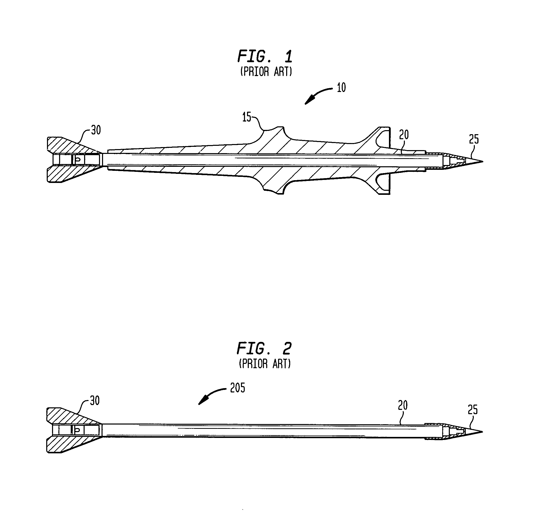
[0041]FIG. 1 is a cut-away profile view of a conventional kinetic energy tactical projectile 10 using a standard sabot 15. The kinetic energy tactical projectile 10 is comprised of a sabot 15, a projectile rod 20, a nose 25, and a fin 30 (known as the in-bore projectile).

[0042]FIG. 2 is a cut-away profile view of a conventional in-flight projectile 205 after the sabot 15 has been discarded, illustrating the prior art design of the rod 20. The rod 20 is the only component of the kinetic energy tactical projectile 10 that does the work of penetrating the target; consequently, the fin 30, the nose 25, and the sabot 15 are parasitic weight.

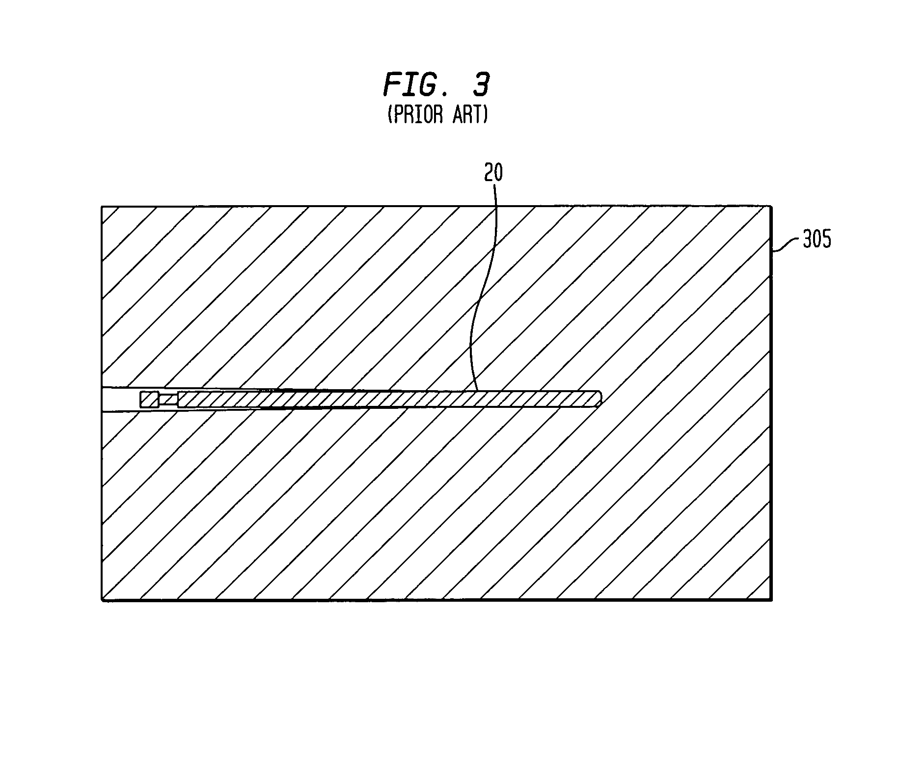
[0043]FIG. 3 illustrates the conventional in-flight projectile 205 penetrating an armored target 305. After impacting the armor of the armored target 305, the rod 20 penetrates the armored target 305 due to its velocity. Factors that determine the depth of penetration of the armored target 305 by the rod 20 comprise characteristics of the rod 20, impa...


PUM


Abstract

A rod sleeve made of smart material sleeves and / or steel sleeves with smart material rings surrounds the rod of a kinetic energy projectile. The rod may be made of DU, tungsten, or other material. Smart materials are materials such as nickel-titanium (nitinol) and copper aluminum nickel (CAN) that can be trained to change to one or more particular shapes at predetermined temperatures. The change in shape occurs on a molecular level, almost instantaneously. The rod sleeve can be made all or in part from smart material. The smart material is trained to shrink at cold temperatures and expand at hot temperatures. The sleeve may then be heated and expanded to allow the sleeve to be pressed on the rod. As the sleeve cools, it compresses and provides required support to rod during gun launch of the kinetic energy projectile. The sleeve heats up while traveling down range due to the aero-ballistic heating of the sleeve material. At this higher temperature, the sleeve expands. Upon projectile impact with the target, the sleeve minimally penetrates the target, allowing the rod to slip supported through the sleeve and penetrate the target. The sleeve supports the rod as it penetrates the target but does not inhibit its penetration, remaining behind as the rod continues to penetrate the target.

Description

FEDERAL RESEARCH STATEMENT[0001]The invention described herein may be manufactured and used by or for the Government of the United States for governmental purposes without payment of any royalties thereon.BACKGROUND OF INVENTION[0002]The present invention generally relates to the field of military ordinance. In particular, it relates to a sleeve for supporting a Kinetic Energy (KE) penetrator rod to increase the rods armor defeat capabilities.[0003]Tactical KE projectiles are well known in the ammunition community and are made in small, medium and large caliber from 20 to 120 mm. FIG. 1 illustrates a cross sectional view of KE projectile 10. The KE projectile 10 is comprised of a sabot 15, rod 20 (also referenced as a penetrator or projectile rod 20), a nose 25, and a fin 30.[0004]The sabot supports the penetrator rod and is typically made of three pieces or petals that are discarded from the rod as soon as the projectile exits the gun tube and moves past the gun gases.[0005]The pro...

Claims


Application Information

Patent Timeline
Patent Type & Authority Patents(United States)
IPC IPC(8): F42B14/06
CPCF42B12/06F42B14/068
Inventor MANOLE, LEONGILMAN, STEWARTLOGSDON, ERNESTVO, DANIEL
Owner THE US GOVERNMENT AS REPRESENTED BY THE SEC OF THE ARMY
Learn More