
Downhole well pump

Active Publication Date: 2007-09-18
BURLINGTON RESOURCES OIL & GAS LP
View PDF16 Cites 70 Cited by
  • Summary
  • Abstract
  • Description
  • Claims
  • Application Information

AI Technical Summary

Benefits of technology

[0010]In yet another embodiment of the invention, a method of producing fluids from a well is provided whereby a gas (preferably the gas from the subject well or wells) is supplied to a pump disposed in a well, the pump including (1) an engine portion that is powered by said pressurized gas and effectuates a rotation of a vertical shaft d

Problems solved by technology

Increasing production demands and the need to extend the economic life of oil and gas wells have long posed a variety of problems.
In time, the bottom hole pressure will decrease to such an extent that the pressure will be insufficient to lift the accumulated fluids to the surface.
In turn, the hydrostatic pressure of the accumulated fluids causes the natural gas produced from the “pay zone” to become substantially reduced or maybe even completely static, reducing or preventing the gases / fluids from flowing into the perforated cased hole and causing the well bore to log off and possibly plugged prematurely for economic reasons.
The most common method is the use of a pump jack (reciprocating pump), but pump jack systems have given rise to additional problems.
Pump jack systems require a large mass of steel to be installed on the surface and comprise several moving parts, including counter balance weights, which pose a significant risk of serious injury to operators.
Additionally, this type of artificial lift system causes wear to well tubing due to pumping rods that are constantly moving up and down inside the tubing.
Consequently, pump jack systems have significant service costs, which negatively impact the economic viability of a well.
Like the pump jack system, the plunger lift system includes numerous supporting equipment elements that must be maintained and replaced regularly to operate effectively, adding significant costs to the production of hydrocarbons from the well and eventually becoming ineffective due to lower reservoir pressures than are required to lift the piston to the surface to evacuate the built up liquids.

Method used


Image

  • Downhole well pump
  • Downhole well pump
  • Downhole well pump

Examples


Embodiment Construction

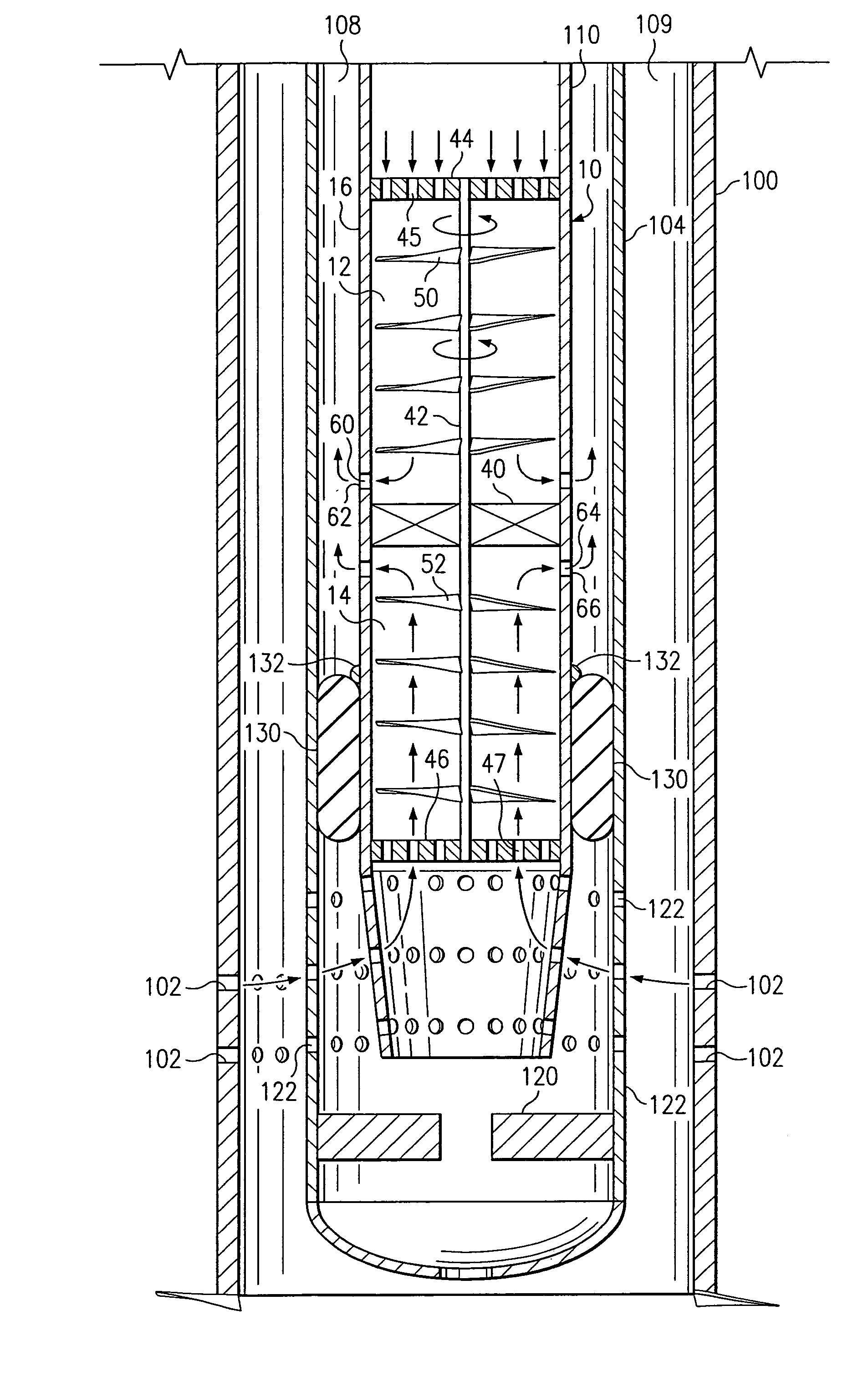
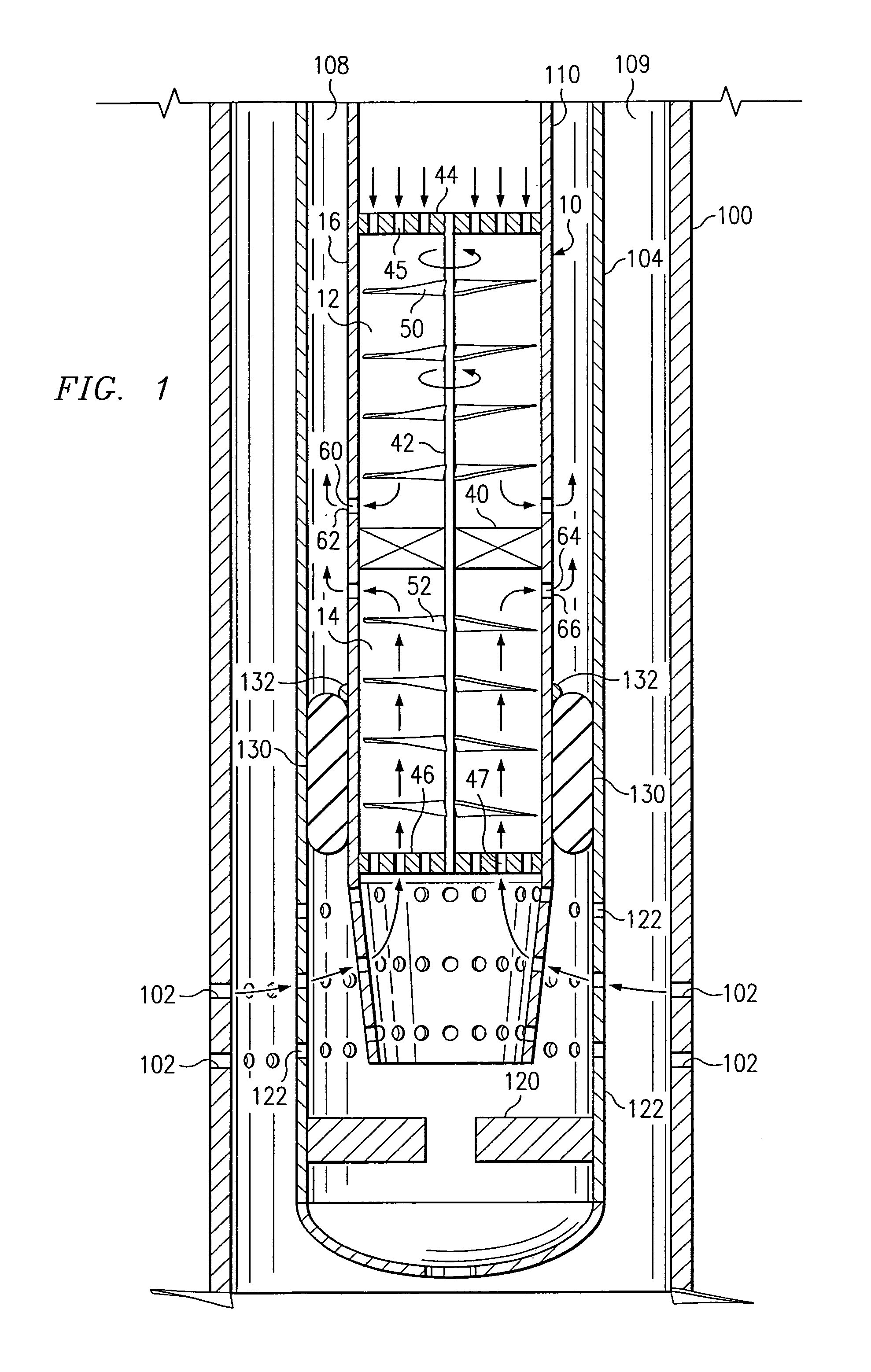
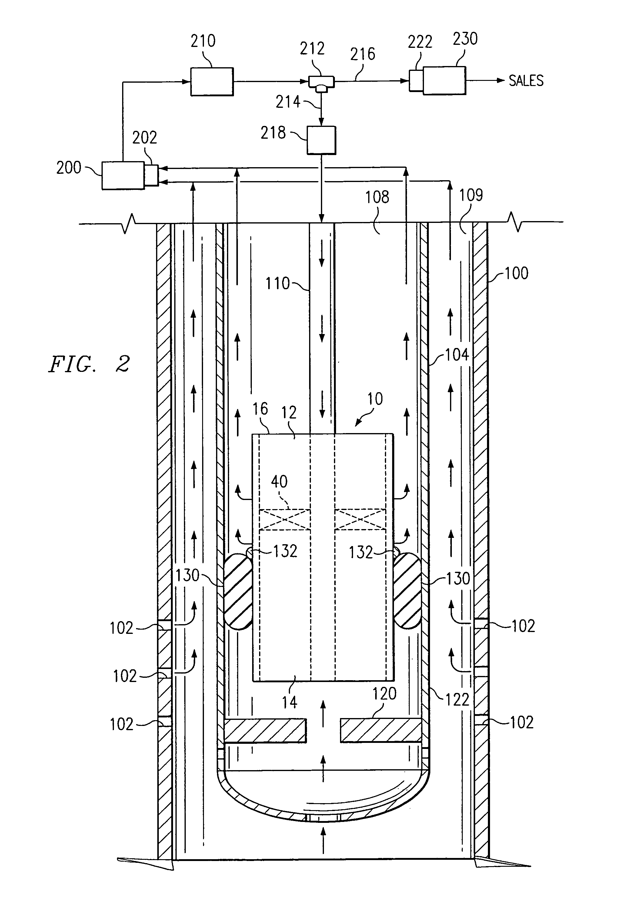
[0017]The present invention is a novel pump and pump system for use in the removal of liquids from wells, especially, but not limited to, wells that have insufficient bottom hole pressure to lift the well liquids out of the well bore and to the surface. Referring to FIGS. 1 and 2, a first preferred embodiment of the present invention shall be described. FIG. 1 and FIG. 2 illustrate a section of a typical hydrocarbon well completion, which includes a casing string 100 with perforations 102 adjacent the hydrocarbon- producing formation and a production tubing string 104 with perforations 106. The production tubing 104 is installed with a down hole standing valve or check valve 120 in the cased hole or well bore. Preferably, the check valve / standing valve 120 is threaded onto the bottom of the production tubing 104, just above a perforated tubing sub 122. This configuration allows for the pump 10 and 1″ tubing 110 to be removed without exposing the formation to any produced fluids and / ...


PUM


Abstract

The pump and pump system of the present invention is designed to remove liquids, gas, sand and coal fines from gas and / or oil well bores. There is a need in the oil and gas industry to develop a more efficient operating pump that is capable of operating in wells that do not have enough bottom hole pressure to lift liquids to the surface causing the well to log off with fluids and if not economic, potentially be plugged prematurely. Additionally, this design will allow the producer the ability to conduct well bore maintenance such as acid flushes for perforation cleaning and scale batch treating for continued scale treatment.

Description

RELATED APPLICATIONS[0001]This application claims the benefit of prior filed copending U.S. Provisional Application No. 60 / 327,803 filed Oct. 9, 2001, and is a 371 of PCT / US02 / 32462 filed Oct. 9, 2002.FIELD OF INVENTION[0002]The present invention relates generally to a pump system for removing natural hydrocarbons or other fluids from a cased hole, i.e. a well bore. More particularly, the present invention relates to a novel downhole, gas-driven pump particularly suitable for removing fluids from gas-producing wells.BACKGROUND OF THE INVENTION[0003]Increasing production demands and the need to extend the economic life of oil and gas wells have long posed a variety of problems. For example, as natural gas is produced, from a reservoir, the pressure within the reservoir decreases over time and some fluids that are entrained in the gas stream with higher pressures, break out due to lower reservoir pressures, and build up within the well bore. In time, the bottom hole pressure will decr...

Claims


Application Information

Patent Timeline
IPC IPC(8): E21B43/00F04B47/08F04D13/04F04D25/04
CPCF04B47/08F04D13/043F04D25/04E21B43/00E21B43/122F04D13/02F04D13/04
Inventor JOHNSON, KENNETH G.
Owner BURLINGTON RESOURCES OIL & GAS LP
Learn More