

Ratiometric clock systems for integrated receivers and associated methods
a technology of ratiometric clock and integrated receiver, which is applied in the direction of radio transmission, electrical equipment, transmission, etc., can solve problems such as significant performance-degrading interferen
- Summary
- Abstract
- Description
- Claims
- Application Information
AI Technical Summary
Benefits of technology
Problems solved by technology
Method used
Image

Examples
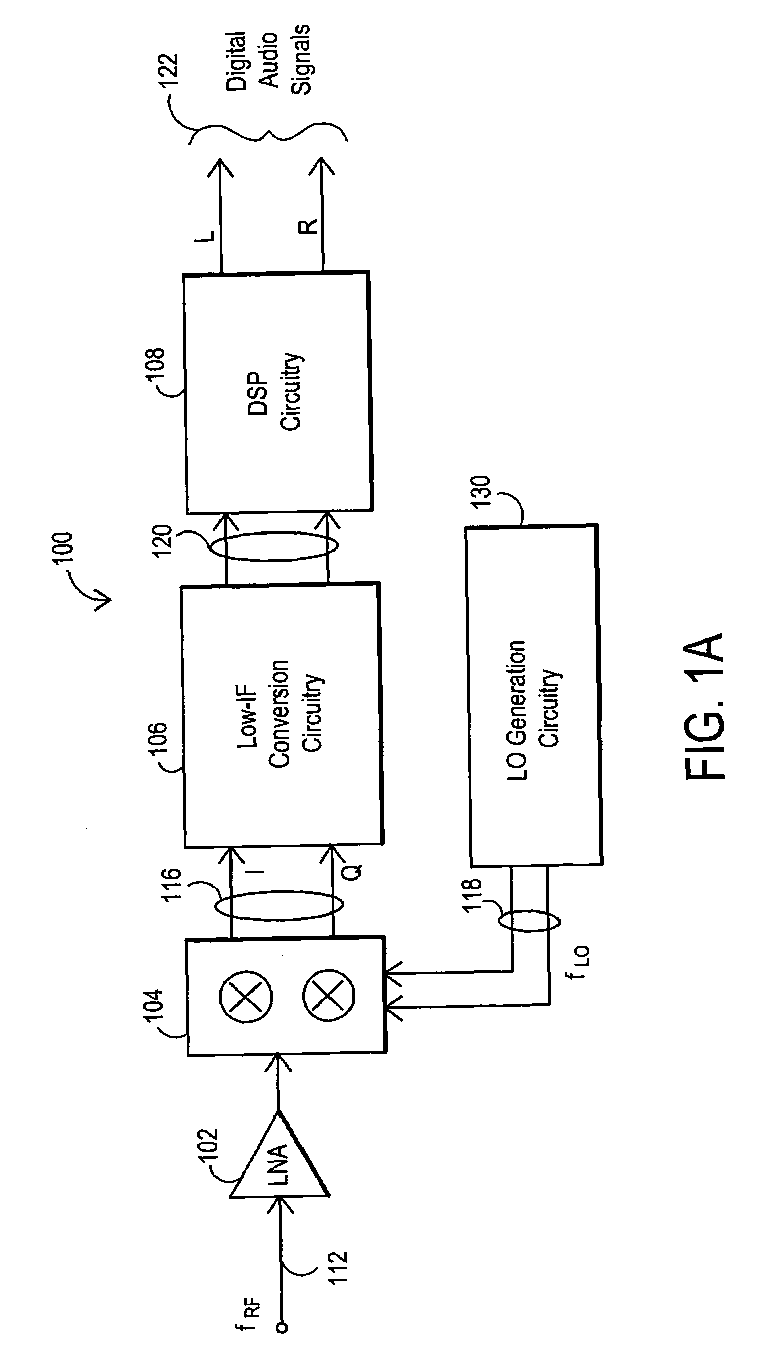
embodiment 100
[0023]FIG. 1A is a block diagram of an embodiment 100 for an integrated terrestrial broadcast receiver that utilizes a low-IF architecture. The input signal spectrum (fRF) 112 is expected to be a radio frequency (RF) signal spectrum that includes a plurality of channels that can be tuned. It is noted that as used herein, a “radio frequency” or RF signal means an electrical signal conveying useful information and having a frequency from about 3 kilohertz (kHz) to thousands of gigahertz (GHz), regardless of the medium through which such signal is conveyed. Thus an RF signal may be transmitted through air, free space, coaxial cable, fiber optic cable, etc. More particularly, the present invention can provide an advantageous architecture for an FM terrestrial broadcast receiver. For purposes of the description below, therefore, the RF signal spectrum (fRF) 112 will be discussed primarily with respect to the RF signal spectrum (fRF) 112 being an FM terrestrial broadcast spectrum that inc...
embodiment 200
[0037]FIG. 2A is a block diagram for an embodiment 200 of an integrated terrestrial broadcast receiver that utilizes a frequency synthesizer 209 and ratiometric clock signals to provide LO mixing signals (fLO) 118 and a digital clock signal (fDIG) 205 for the receiver circuitry. As with FIG. 1A, an RF input signal spectrum (fRF) 112 is received by a low noise amplifier (LNA) 102 and processed by mixer 104 to generate real (I) and imaginary (Q) signals 116. Low-IF conversion circuitry 106 and DSP circuitry 108 processes these signals to produce left (L) and right (R) digital audio output signals 122. In addition, as shown in FIG. 1B, these left (L) and right (R) digital audio output signals 122 can be processed with additional circuitry, as represented by digital-to-analog conversion (DAC) circuits 170 and 172, to produce left (L) and right (R) analog output signals 212.
[0038]As further depicted in embodiment 200 of FIG. 2A, a phase shift block 132 can be utilized, and this phase shi...
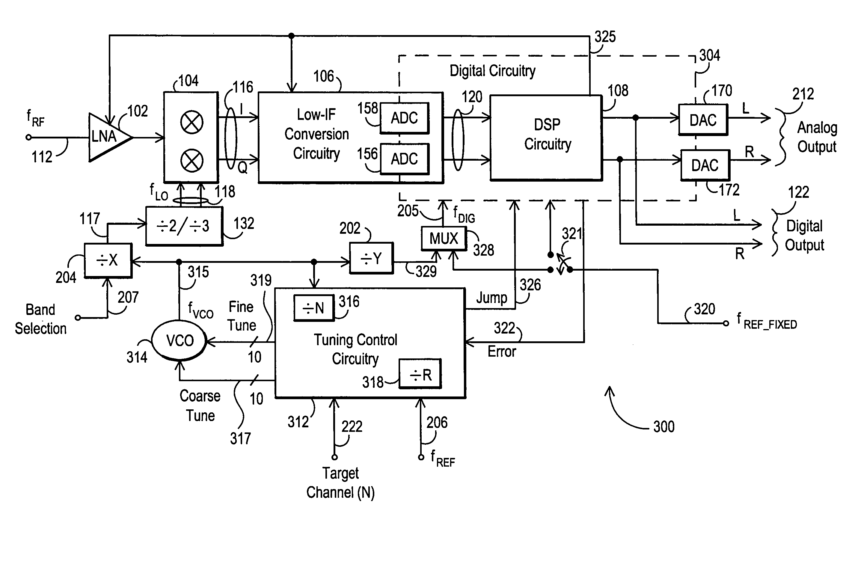
embodiment 300
[0046]FIG. 3A is a block diagram of an alternative embodiment 300 for an integrated terrestrial broadcast receiver that utilizes tuning control circuitry 312 and a ratiometric clock system to provide an LO mixing signals (fLO) 118 and a digital clock signal (fDIG) 205 for the receiver circuitry. As with FIGS. 1 and 2A, an RF input signal spectrum (fRF) 112 is received by a low noise amplifier (LNA) 102 and processed by mixer 104 to generate real (I) and an imaginary (Q) signals 116. Low-IF conversion circuitry 106 and DSP circuitry 108 process these signals to produce left (L) and right (R) digital audio output signals 122. In addition, as shown in FIG. 2A, these left (L) and right (R) digital audio output signals 122 can be processed with additional circuitry, as represented by digital-to-analog conversion (DAC) circuits 170 and 172, to produce left (L) and right (R) analog output signals 212. Also, as in FIG. 2A, the LO input signal (fLO) 118 and the digital clock signal (fDIG) 20...
PUM
 Abstract
Description
Claims
Application Information