Pressure activated shutoff valve

Inactive Publication Date: 2007-09-25
NELSON BURT
View PDF15 Cites 6 Cited by
  • Summary
  • Abstract
  • Description
  • Claims
  • Application Information

AI Technical Summary

Benefits of technology

[0027]The user will be alerted by having sodas low carbonated (flat). The soda systems in use today can require up to 110 psi to operate properly. The user will contact CO2 supplier who will troubleshoot problem over the phone and instruct the user to close ball valve and call beverage vendor(s). This will save CO2 supplier and user great cost by preventing service calls related to outside vendor equipment failure. After repair

Problems solved by technology

Causes for such loss in head pressure are normally caused by sudden leaks in one or more of the devices using CO2 vapor to deliver/p

Method used


Image

  • Pressure activated shutoff valve
  • Pressure activated shutoff valve
  • Pressure activated shutoff valve

Examples


Example

[0083]The following discussion describes in detail one embodiment of the invention (and several variations of that embodiment). This discussion should not be construed, however, as limiting the invention to those particular embodiments, practitioners skilled in the art will recognize numerous other embodiments as well. For definition of the complete scope of the invention, the reader is directed to appended claims.

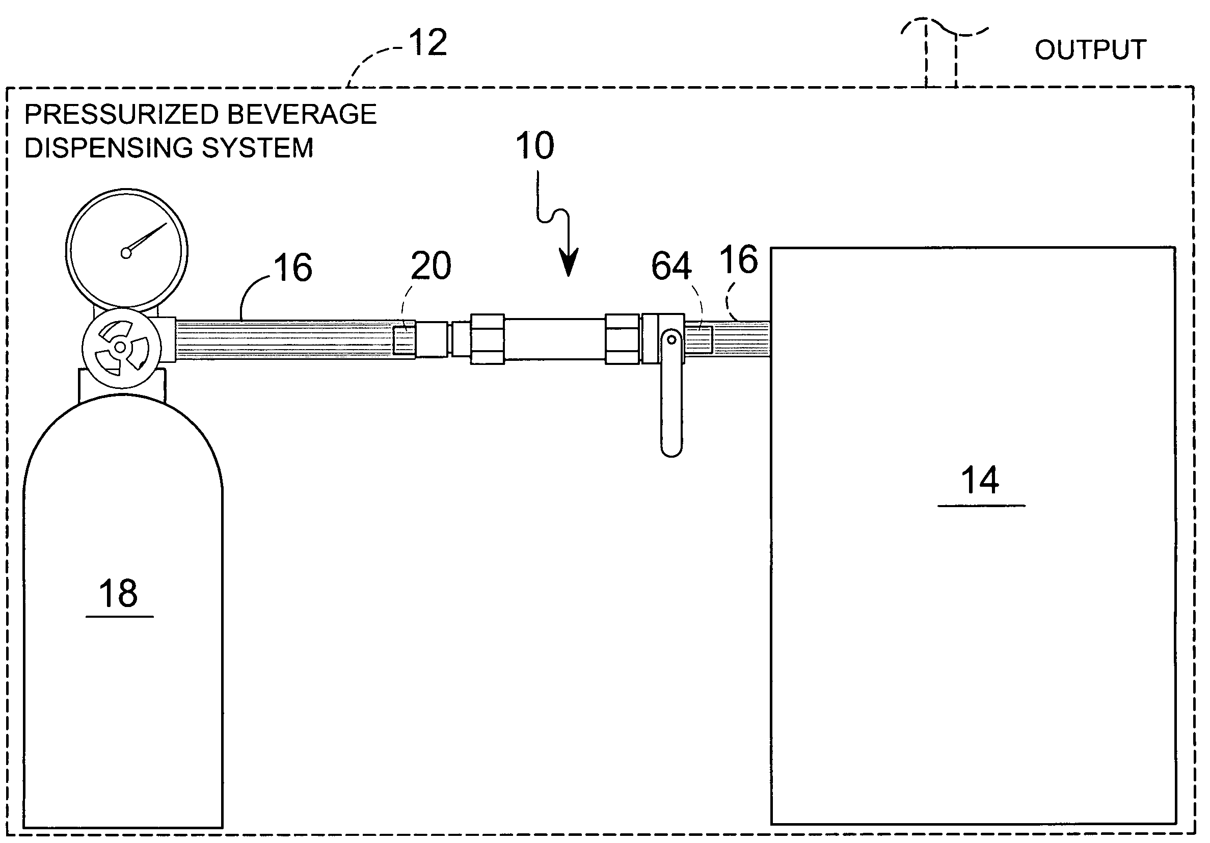
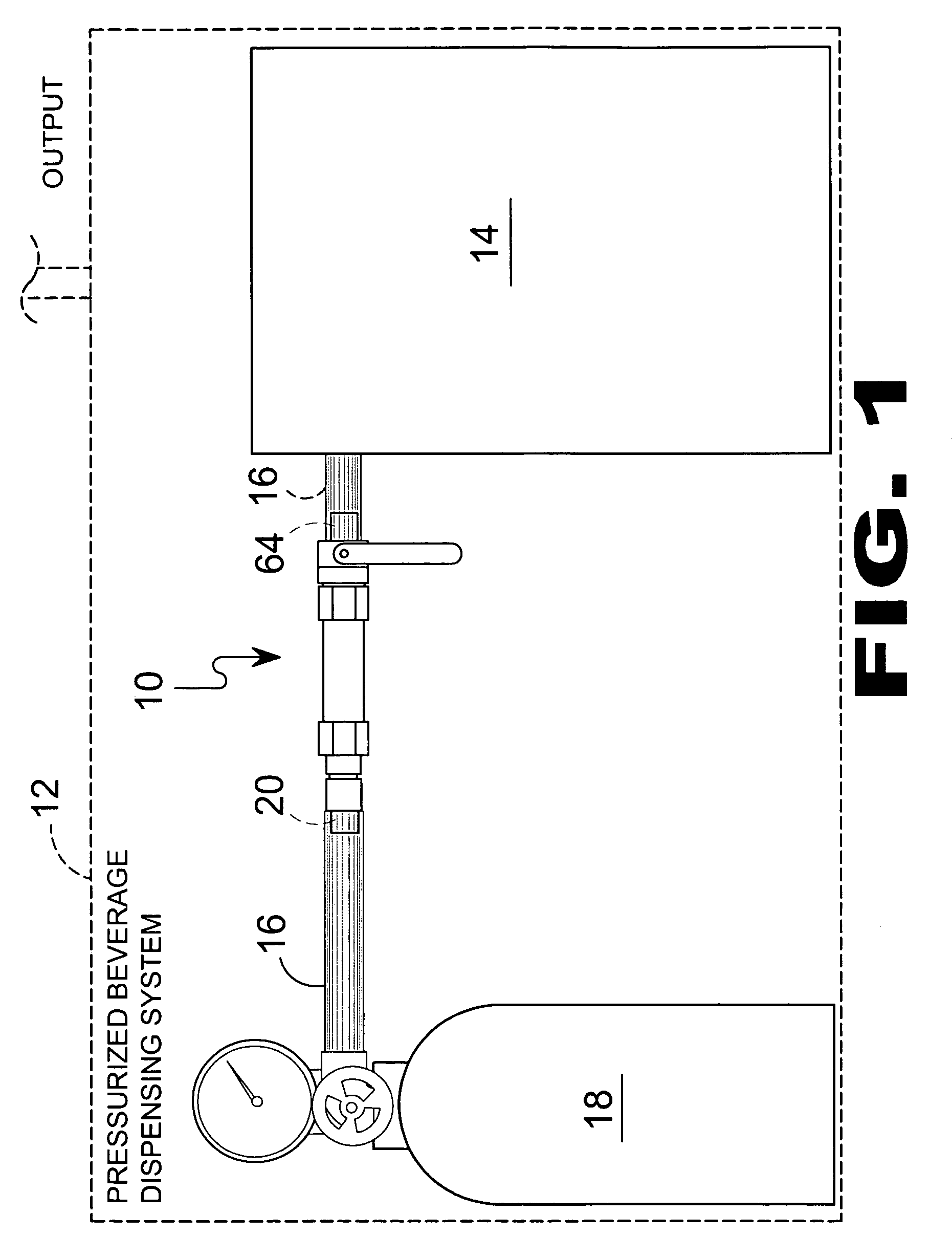
[0084]Referring to FIG. 1, shown is a flow diagram of the present invention. Depicted is a flow diagram of the pressure activated shutoff value 10 for a pressurized beverage dispensing system 12 of the present invention. The pressure activated shutoff valve 10 is positioned within gas supply line 16 extending between gas source 18 and beverage source 14 using nipple 20 and 74. Once positioned therein the apparatus 10 will maintain a base pressure in a pressurized system, thereby maintaining a predetermined critical state to prevent crystallization of a liquified gas 18, in...


PUM


Abstract

An apparatus for providing a pressurized gas inline valve assembly incorporating a check valve to maintain pressure above a selectable psi and a ball valve for selectively shutting off gas flow. The apparatus is preferably positioned approximate the gas source in a beverage dispensing system that uses carbon dioxide for carbonation, preservative and propellant. Preferably, the apparatus is designed to maintain the system pressure above the threshold pressure that when below said threshold pressure the carbon dioxide would revert to its inoperative dry ice solid state as opposed to its operative liquid state.

Description

BACKGROUND OF THE INVENTION[0001]1. Field of the Invention[0002]The present invention relates generally to shutoff valves and, more specifically, to a pressure activated shutoff valve that will maintain a base pressure in a pressurized system thereby maintaining a predetermined critical state to prevent crystallization of a liquified gas, in this case carbon dioxide from reverting to a solid state (dry ice). Furthermore, the present invention provides a manual cut-off switch to sever gas service to remote dispensing modules.[0003]2. Description of the Prior Art[0004]There are other valve devices designed for pressurized systems. Typical of these is U.S. Pat. No. 1,243,068 issued to Humphrey on Oct. 16, 1917.[0005]Another patent was issued to Briggs on Jun. 27, 1967 as U.S. Pat. No. 3,327,521. Yet another U.S. Pat. No. 4,409,817 was issued to Edwards, Jr. on Oct. 18, 1983 and still yet another was issued on Nov. 22, 1994 to Ueda, et al. as U.S. Pat. No. 5,365,772.[0006]Another patent...

Claims


Application Information

Patent Timeline
IPC IPC(8): B65D83/44
CPCB67D1/0406B67D1/1252F17C2201/0114F17C2201/0119F17C2201/056F17C2201/058F17C2203/0391F17C2205/0329F17C2205/0335F17C2205/0338F17C2205/0364F17C2221/013F17C2223/0153F17C2223/0192F17C2227/048F17C2260/032Y10T137/87917Y10T137/88054
Inventor NELSON, BURT
Owner NELSON BURT
Why Eureka
Try Eureka