Barometric pressure correction based on remote sources of information

Inactive Publication Date: 2007-09-25
REMON MEDICAL TECH
View PDF16 Cites 139 Cited by
  • Summary
  • Abstract
  • Description
  • Claims
  • Application Information

AI Technical Summary

Benefits of technology

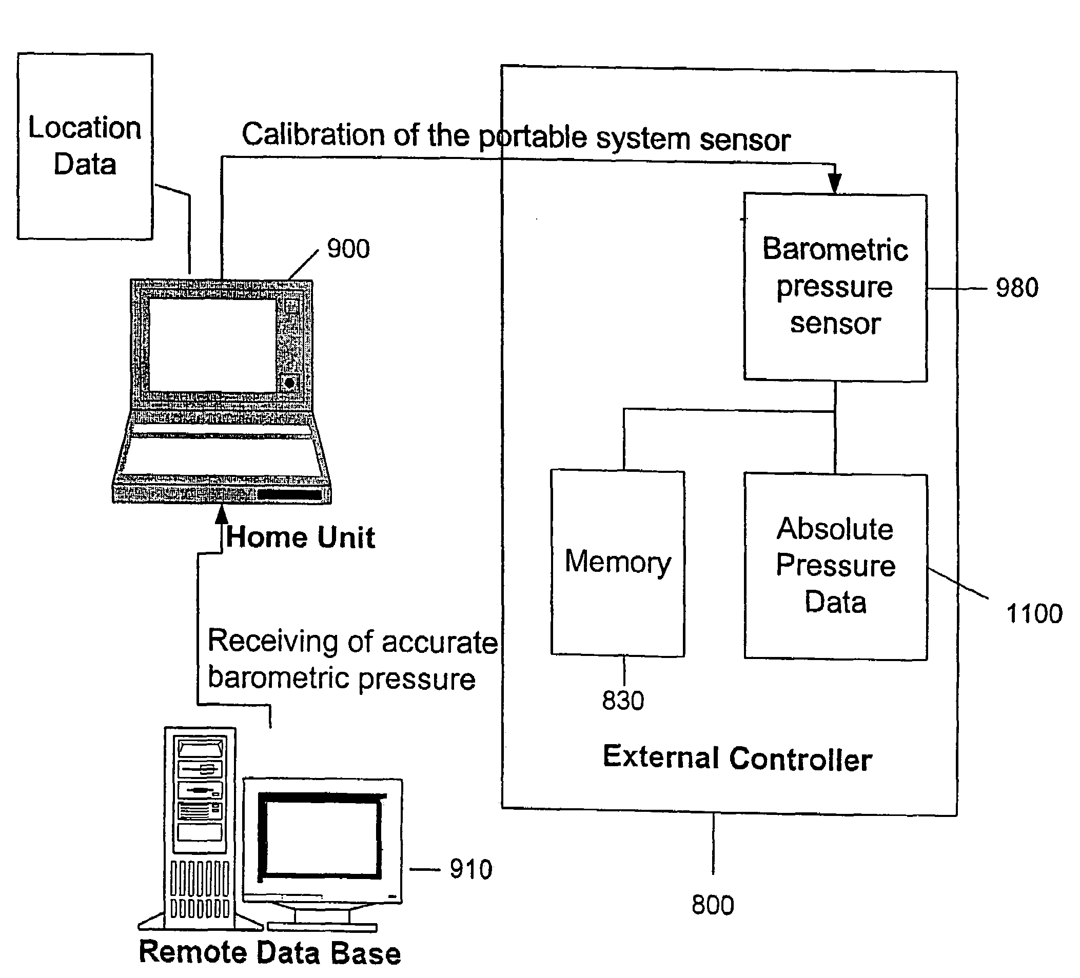
[0007]The invention is generally directed to systems and methods for measuring pressure in a sealed or isolated system by converting or correcting data received from the sealed or otherwise isolated system using one or more remote databases. This generally involves a sensor placed within an isolated or enclosed system. Such enclosed systems can include anatomical structures such as blood vessels within a human circulatory system or other anatomical locations. They can also include isolated systems associated with automobiles, such as braking systems, cooling systems, cylinders and combustion chambers of an internal combustion engine, air intake systems, fuel systems including carburetors, electrical systems, air conditioning and heating systems, etc. The sensors can include those that are capable of measuring pressure, temperature, electrical impedance, position, strain, pH, fluid flow, chemical properties, electrical properties, magnetic properties and the like. An external monitor is used to communicate with the isolated sensor and obtain data about the parameters that are monitored by the sensor. The communication means can be wireless and can involve th

Problems solved by technology

RF energy, however, may only penetrate a few millimeters into a body, because of the body's dielectric nature, and therefore may not be able to communicate effectively with an implant that is located deep within the body.
In addition, although an RF transmitter may be able to induce a current within an implant, the implant's receiving antenna, generally a low impedance coil, may generate a voltage that is too low to provide a reliable switching mechanism.
The presence of extern

Method used


Image

  • Barometric pressure correction based on remote sources of information
  • Barometric pressure correction based on remote sources of information
  • Barometric pressure correction based on remote sources of information

Examples


first embodiment

[0095]FIG. 9 shows a full-bridge rectifier 40′ that may be provided. The energy transducer 14 and energy storage device 16 may be connected to the rectifier 40′ such that AC current generated by the energy transducer 14 is converted into DC current for charging the energy storage device 16. The full-bridge configuration of the rectifier 40′ may yield relatively high current and power efficiency that may be suitable for “full-duplex” operation of the energy transducer 14, i.e., where the energy transducer 14 simultaneously converts external acoustic energy into electrical energy and transmits an acoustic signal.

second embodiment

[0096]FIG. 10 shows a voltage-doubler rectifier 40″ that may be used. The configuration of this rectifier 40″ may yield less current than the rectifier 40′ shown in FIG. 9, although it may generate a relatively higher voltage for a given acoustic excitation of the energy transducer 14. This rectifier 40″ may be better suited for “half-duplex” operation, i.e., where the energizing and transmitting functions of the energy transducer 14 are temporally distinct. This embodiment may also only require two diodes to operate and may keep one side of the energy transducer 14 substantially grounded, thereby simplifying construction of the implant 10.

[0097]Alternatively, other rectification circuits (not shown) may be used, including Schottky diodes, voltage triplers or other multiplier circuits, and the like. In addition, the rectifier 40 may include an overvoltage protector (not shown), which may prevent the energy storage device 16 from overcharging, e.g., to unsafe levels. For example, the...


PUM


Abstract

The invention includes systems and methods for converting absolute pressure data acquired in anatomical environments to gauge pressure data using an implant configured to monitor pressure. The implant is configured to communicate with an external controller, which is configured to communicate with a remote microprocessor that includes real-time barometric pressure data for one or more geographic locations.

Description

RELATED APPLICATION DATA[0001]This is a continuation-in-part of U.S. application Ser. No. 09 / 989,912, filed Nov. 19, 2001 now U.S. Pat. No. 7,024,248, which is a continuation-in-part of U.S. application Ser. No. 09 / 690,615, filed Oct. 16, 2000 now U.S. Pat. No 6,628,989. This is also a continuation-in-part of U.S. application Ser. No. 09 / 888,272, filed Jun. 21, 2001 now U.S. Pat. No. 6,764,446, which is a continuation-in-part of U.S. application Ser. No. 09 / 690,615, filed Oct. 16, 2000. The aforementioned applications are all incorporated herein by reference in their entireties.FIELD OF THE INVENTION[0002]The present invention relates generally to barometric pressure correction in implantable biosensors, and more particularly to barometric pressure correction for implantable pressure sensors based on remote sources of information, including remote databases and web sites.BACKGROUND OF THE INVENTION[0003]Devices are known that may be implanted within a patient's body for monitoring o...

Claims


Application Information

Patent Timeline
IPC IPC(8): A61B5/00A61B5/0215A61B5/03A61B5/07A61B8/00A61N1/08A61N1/372
CPCA61B5/00A61B5/0031A61B5/02A61B5/0215A61B5/031A61B5/076A61B5/1112A61B5/14539A61B5/4839A61B8/56A61N1/08A61N1/37217A61B8/4281A61B2560/0209A61B2560/0214A61B2560/0219A61B2560/0242A61B2560/0257A61B2560/0412A61B2562/028A61N1/05A61N1/37235A61N1/37252A61N1/37282
Inventor PENNER, AVI
Owner REMON MEDICAL TECH
Why Eureka
Try Eureka