

Cogeneration system
a technology of cogeneration system and heat pump, which is applied in the direction of heat pumps, defrosting, and domestic cooling devices, can solve the problems of low system efficiency of cogeneration system, and achieve the effects of maximizing system efficiency, enhancing heating performance of heat pump type air conditioner including indoor heat exchanger, and maximizing system efficiency
- Summary
- Abstract
- Description
- Claims
- Application Information
AI Technical Summary
Benefits of technology
Problems solved by technology
Method used
Image

Examples
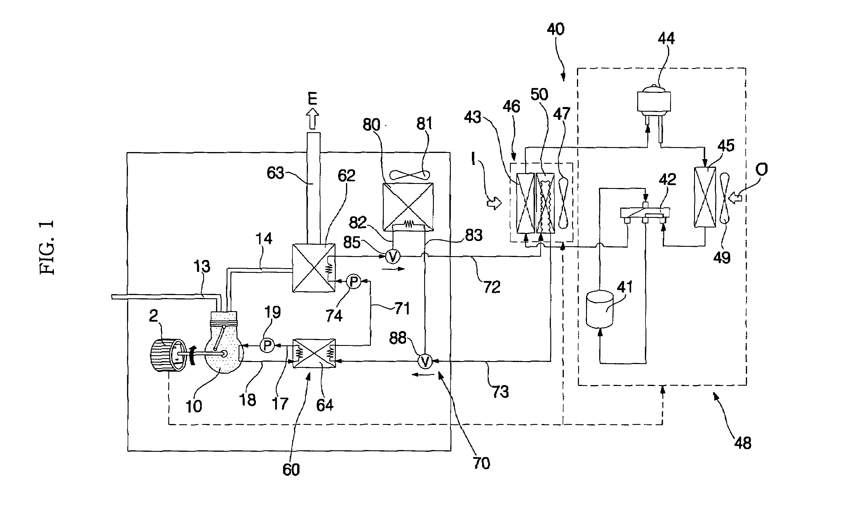
first embodiment
[0044]As shown in FIGS. 1 and 2, the cogeneration system according to the present invention includes a generator 2, and a drive source 10, which operates to drive the generator 2 for generation of electricity, and generates waste heat during operation thereof. The cogeneration system also includes a heat pump type air conditioner 40, which includes a compressor 41, a 4-way valve 42, an indoor heat exchanger 43, an expansion device 44, and an outdoor heat exchanger 45, a heater 50 adapted to heat air, which has passed around the indoor heat exchanger 43 after completing heat exchange with the indoor heat exchanger 43, a waste heat recoverer 60 adapted to recover the waste heat of the drive source 10, and to supply the recovered waste heat to the heater 50.
[0045]The generator 2 may be an AC generator or a DC generator. The generator 2 includes a rotor coupled to an output shaft of the drive source 10 so that the generator 2 generates electricity during rotation of the output shaft.
[00...
fourth embodiment
[0133]FIG. 7 is a schematic diagram of a cogeneration system according to the present invention, illustrating a state in which the cogeneration system operates in a heating mode.
[0134]As shown in FIG. 7, the cogeneration system according to this embodiment includes a plurality of drive sources 10, 10′ . . . , and a plurality of generators 2, 2′ . . . coupled to respective rotating shafts of the drive sources 10, 10′ . . . .
[0135]Only one or at least two of the drive sources 10, 10′ . . . operate in accordance with the cooling or heating load of the heat pump type air conditioner 40.
[0136]Fuel tubes 13, 13′ . . . are connected to respective drive sources 10, 10′ . . . Exhaust tubes 14, 14′ are also connected to respective drive sources 10, 10′ . . . Also, pairs of cooling water circulation conduits 17 and 18, 17′ and 18′ . . . are connected to respective drive sources 10, 10′ . . . .
[0137]The exhaust tubes 14, 14′ . . . are connected in parallel.
[0138]The cooling water circulation co...
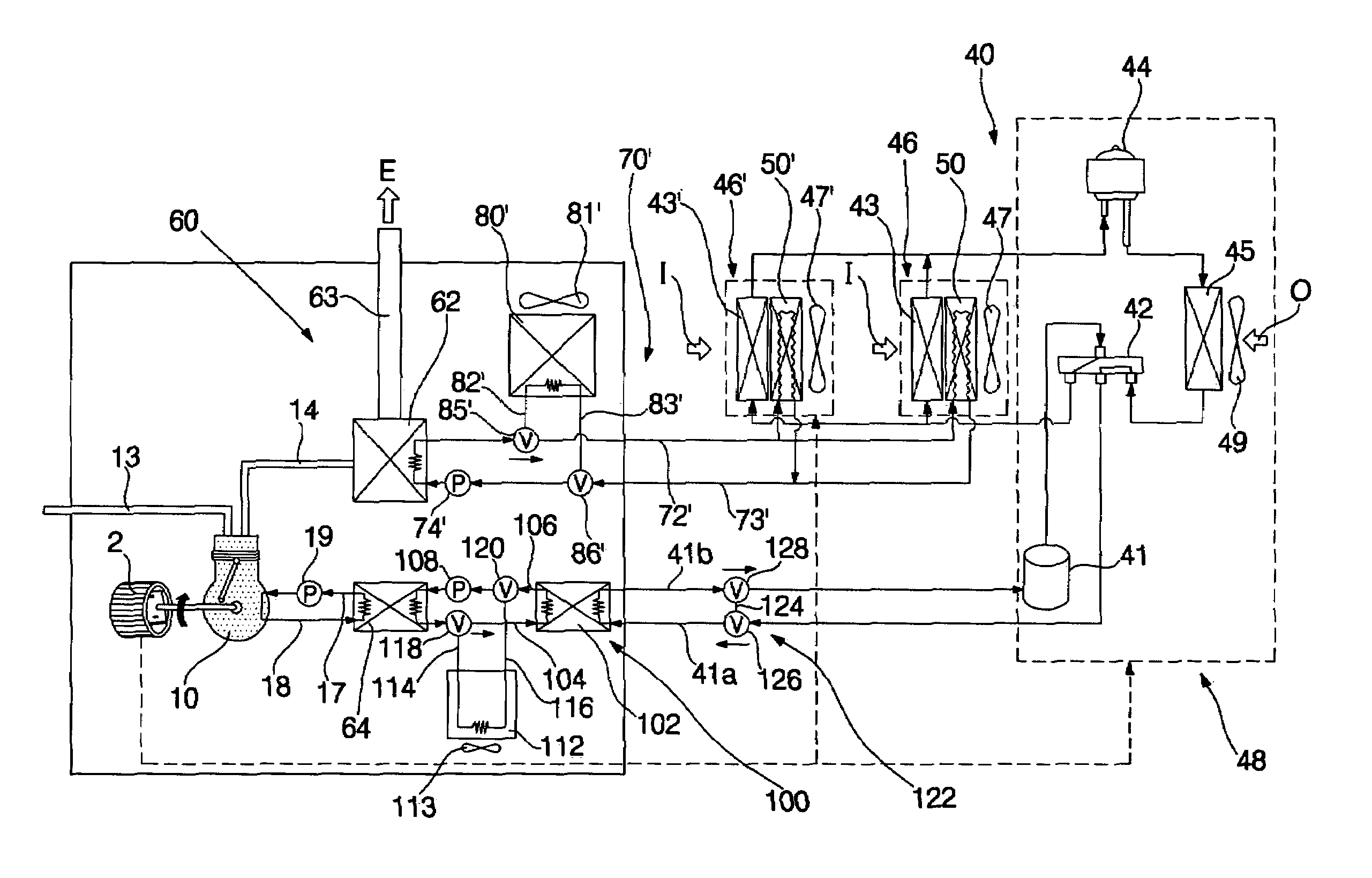
fifth embodiment
[0141]FIG. 8 is a schematic diagram of a cogeneration system according to the present invention, illustrating a state in which the cogeneration system operates in a heating mode.
[0142]As shown in FIG. 8, the heat pump type air conditioner 40 of the cogeneration system according to this embodiment, is of a multi-type. That is, the heat pump type air conditioner 40 includes a plurality of indoor units 46, 46′ . . . , and a single outdoor unit 48, to which the indoor units 46, 46′ . . . are connected. The indoor units 46, 46′ . . . include indoor heat exchangers 43, 43′ . . . , which are connected in parallel, respectively.
[0143]The indoor units 46, 46′ . . . also include indoor fans 47, 47′ . . . , respectively.
[0144]Heaters 50, 50′ . . . are installed in respective indoor units 46, 46′ . . . .
[0145]The heat medium circulation conduits 72′ and 73′ are connected to each of the heaters 50, 50′ . . . .
[0146]The cogeneration system of this embodiment has the same configuration and functio...
PUM
 Abstract
Description
Claims
Application Information