

Control circuit for a common line
a control circuit and common line technology, applied in the field of liquid crystal devices, can solve the problems of large power consumption, serious affecting the image quality of lcd, and perturbation of the potential difference of liquid crystal pixels, so as to prevent the power consumption problem and the high impedance of the connected common line
- Summary
- Abstract
- Description
- Claims
- Application Information
AI Technical Summary
Benefits of technology
Problems solved by technology
Method used
Image

Examples
embodiment 1
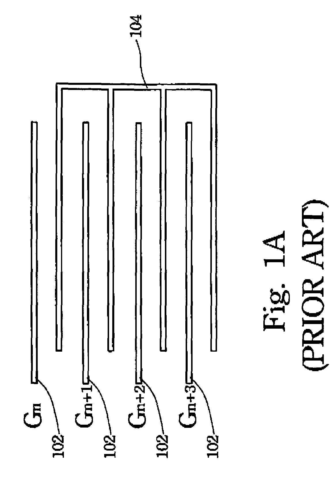
[0041]As shown in FIG. 2A, the scan lines 102 (Gn˜Gn+3) are used to independently control the thin film transistors (TFT's) of liquid crystal pixels in different rows. Moreover, the common lines 106 (Sn˜Sn+3) of the liquid crystal pixels in different rows are also independent; none of them is connected together. That is, the invention can independently change the potentials of the common electrodes for the liquid crystal pixels in different rows. When the common electrode potential of the liquid crystal pixels in a row is changed, those of other liquid crystal pixels do not vary at all.
[0042]FIG. 7 is a schematic view of the control circuit according to a preferred embodiment of the invention. The control circuit 700 in FIG. 7 is used to control the common line 106 in FIG. 2A. A first input element 712 is arranged to receive a first switching signal at a terminal 706, and a second input element 714 is arranged to receive a second switching signal at a terminal 708. The invention use...
embodiment 2
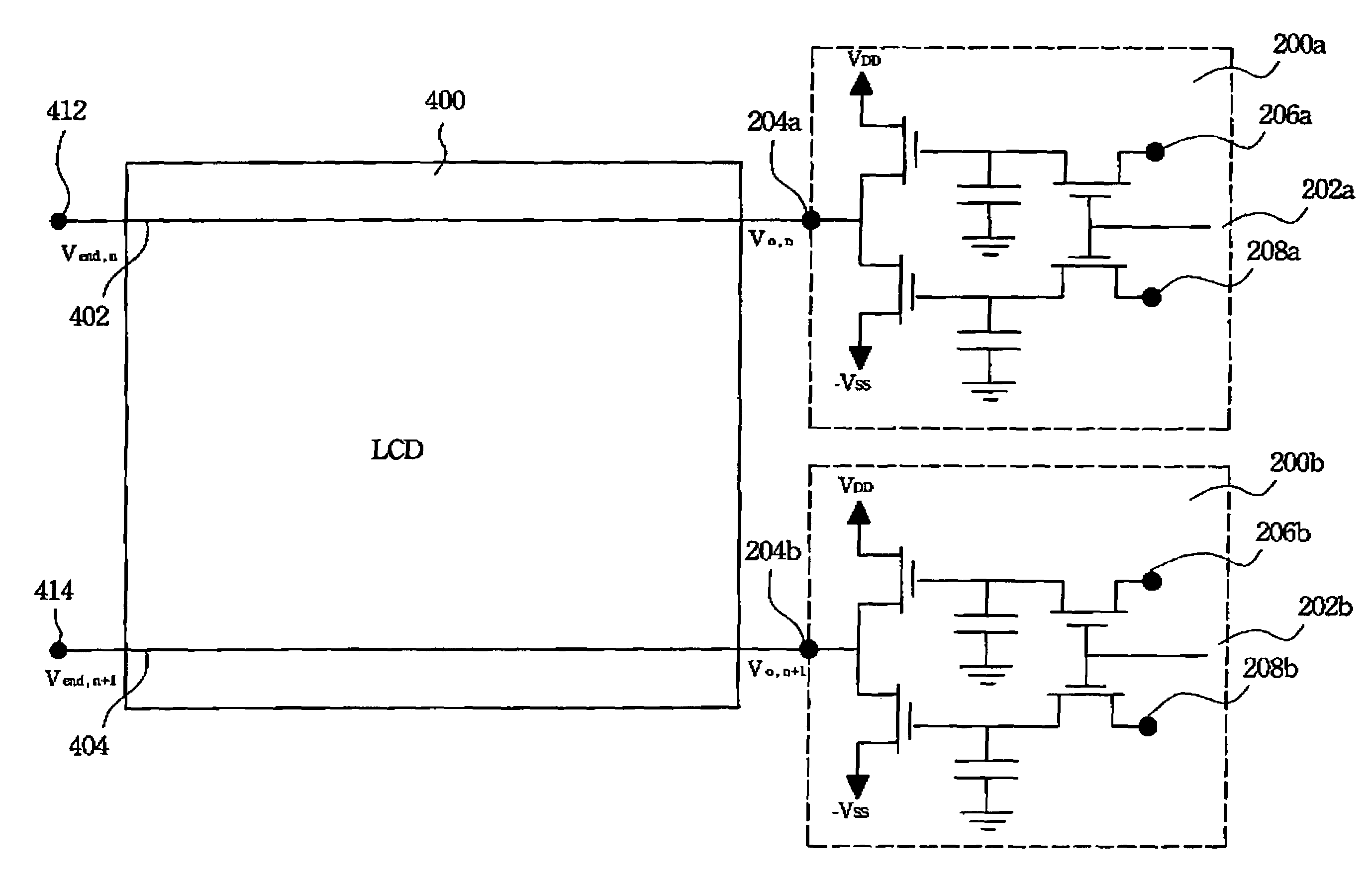
[0058]In FIG. 4, we show an LCD using the above-mentioned control circuit to control the common lines. Here we only draw two adjacent common lines to explain the configuration of the disclosed control circuit and the operation method. In general, the LCD 400 has several common lines (only two adjacent ones 402, 404 being shown in the drawing). The common lines 402, 404 are connected to the control circuits 200a, 200b at the nodes 204a, 204b, respectively. The control circuits 200a, 200b are the same as that in FIG. 2B. Therefore, we can use the control circuits 200a, 200b to control the voltages on the common lines 402, 404 in the LCD 400, respectively.
[0059]In the following, we use FIGS. 3A and 3B to discuss how to change the voltages on the two adjacent common lines using the invention. In existing LCD's, to render a perfect image display, the voltages on the liquid crystal pixels in different rows can be “+−+−”, “++−−”, or other combinations. Thus, the voltages on two adjacent co...
embodiment 3
[0064]We have described how to control the voltages on two adjacent common lines in the previous embodiment. According to another embodiment of the invention, the voltages on the terminals 206a, 208a, 206b, 208b are provided by the common lines in the preceding few rows. From the embodiments shown in FIGS. 3A, 3B, and 2B, we know that when the voltage at the terminal 206 is high SH, the voltage at the node 204 (connecting to the common line) is VDD. When the voltage at the terminal 206 is low SL, the voltage at the node 204 is −VSS.
[0065]From the above description, we see that the common lines in the LCD have high or low (positive or negative) voltages that vary as the switching signals changes with frame time. Therefore, the first switching signal and the second switching signal required by the disclosed control circuit may be provided by the common lines of the preceding few rows connected in cascade. The common lines of which preceding rows selected to be cascaded are determined ...
PUM
 Abstract
Description
Claims
Application Information