Antenna amplifier and shared antenna amplifier
a technology of antenna amplifier and amplifier, which is applied in the direction of radio transmission, electrical equipment, transmission monitoring, etc., can solve problems such as distortion and signal suppression, and achieve the effect of reducing distortion and signal suppression, and high sensitivity
- Summary
- Abstract
- Description
- Claims
- Application Information
AI Technical Summary
Benefits of technology
Problems solved by technology
Method used
Image
Examples
first embodiment
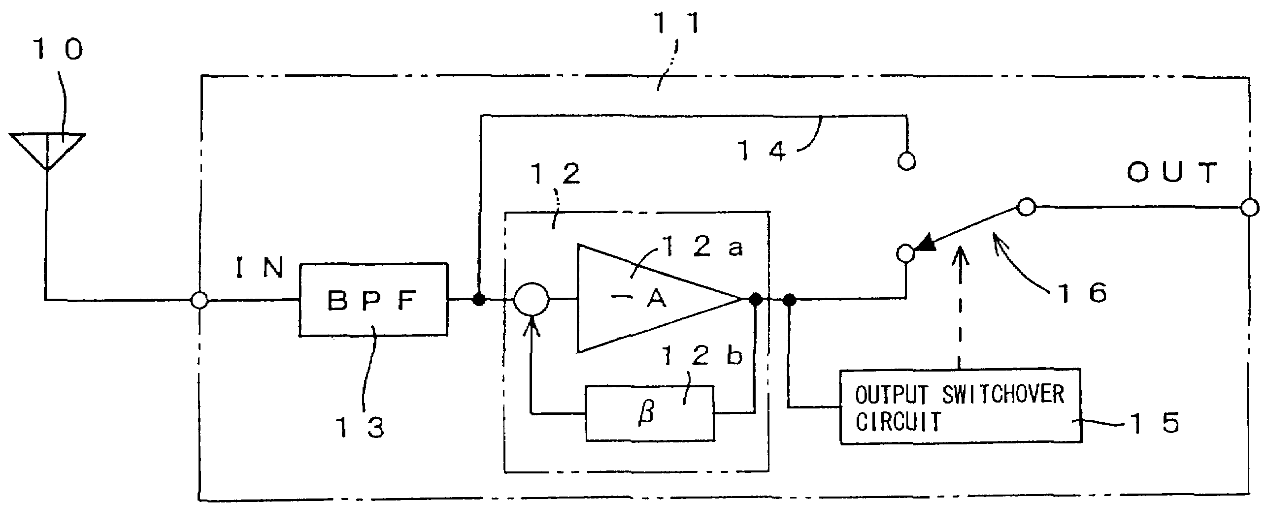
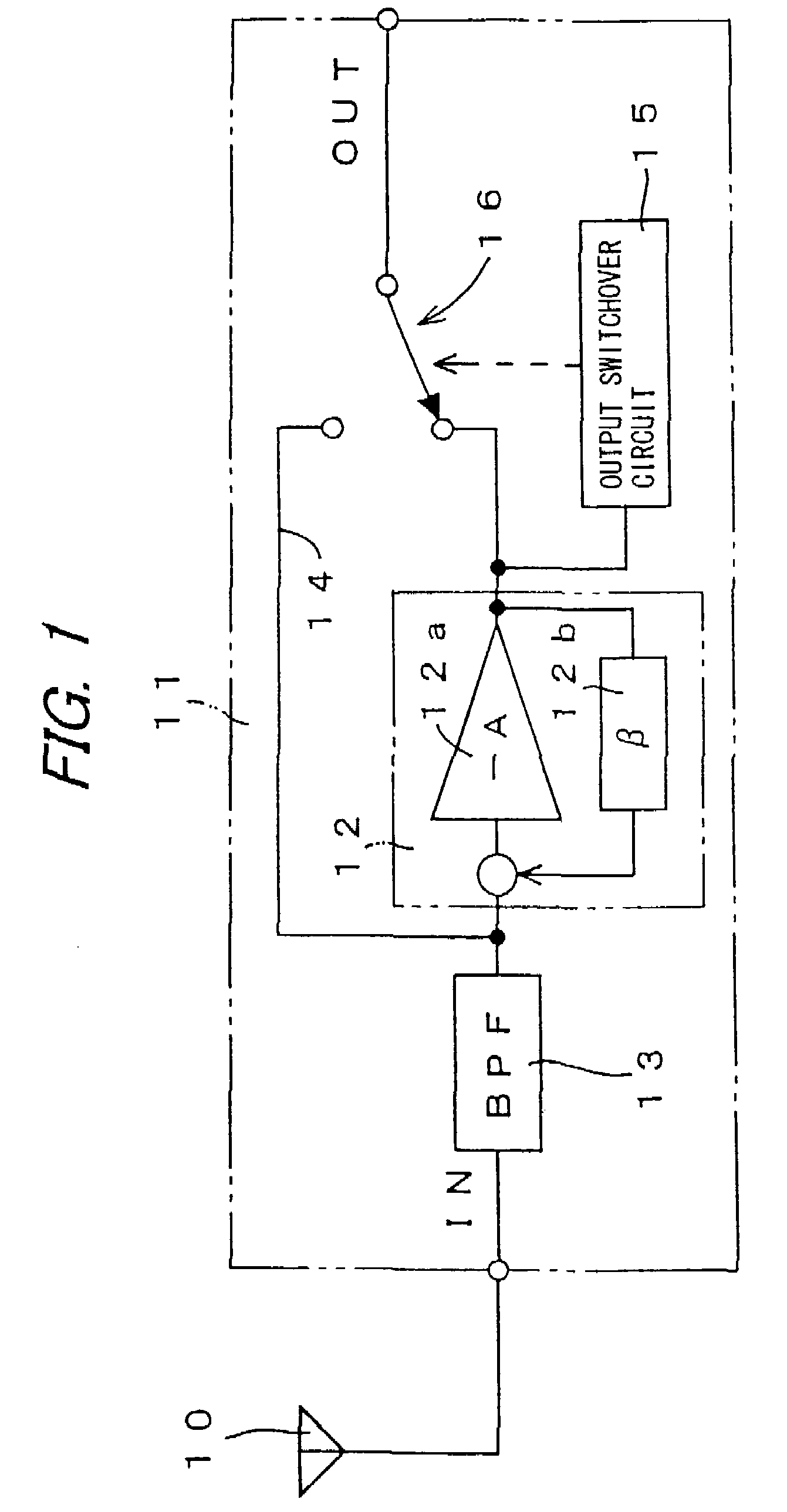
[0058]FIG. 1 schematically shows the electrical configuration of an antenna amplifier 11 which is the invention, and which is disposed in the vicinity of an antenna 10 to amplify a weak high-frequency signal received by the antenna 10. The antenna amplifier 11 includes an amplifier 12, a band pass filter (abbreviated to “BPF”) 13, a through-circuit 14, an output switchover circuit 15, and a switch circuit 16. The amplifier 12 includes: an inverting amplifier 12a in which the absolute value of the signal amplification factor is“A”, and which is therefore indicated by “−A”; and a negative feedback circuit 12b which has a feedback factor β. The amplifier 12 amplifies the high-frequency signal. The BPF 13 selects a frequency band of the high-frequency signal which is inputted from the antenna 10 to the amplifier 12. The frequency band which is selected by the BPF 13 is so wide that not only the target received signal but also a signal which may cause interference are passed through the ...
second embodiment
[0068]FIG. 4 schematically shows the electrical configuration of an antenna amplifier 21 which is the invention. In the embodiment, components corresponding to those of the embodiment of FIG. 1 are denoted by the same reference numerals, and duplicate description is omitted. In the embodiment, an ATT circuit 22 is inserted into the input side of the amplifier 12 to attenuate a signal, so that the whole gain of the combination of the ATT circuit 22 and the amplifier 12 can be reduced. In the ATT circuit 22, a signal is attenuated on the basis of the division ratio of resistors 23 and 24. When the input signal level is low, an input switchover circuit 25 controls a switch circuit 26 so as to be switched to the input side of the amplifier 12, thereby producing a state where the resistor 23 is short-circuited. In this state, the input signal is inputted to the amplifier 12 without being attenuated. When the input switchover circuit 25 controls the switch circuit 26 so as to be disconnec...
third embodiment
[0076]FIG. 7 schematically shows the electrical configuration of an antenna amplifier 51 which is the invention. In the embodiment, components corresponding to those of the embodiments of FIG. 1 or 4 are denoted by the same reference numerals, and duplicate description is omitted. In the embodiment, the gain of an amplifier 52 can be switched in at least two steps in accordance with a control signal from the outside. The switching of the gain may be performed by changing the gain of the amplifier 52 itself stepwise or continuously, or by maintaining the gain of the amplifier 52 constant and changing the signal attenuation factor by an ATT circuit or the like on the input side in the same manner as the embodiment of FIG. 4.
[0077]As described above, the output of the amplifier 52 contains distortion components due to intermodulation or cross modulation. Such distortion components are reflected to low-frequency components of the output of the amplifier 52. The low-frequency components ...
PUM
 Abstract
Description
Claims
Application Information
 - R&D
- Intellectual Property
- Life Sciences
- Materials
- Tech Scout
- Unparalleled Data Quality
- Higher Quality Content
- 60% Fewer Hallucinations
Browse by: Latest US Patents, China's latest patents, Technical Efficacy Thesaurus, Application Domain, Technology Topic, Popular Technical Reports.
© 2025 PatSnap. All rights reserved.Legal|Privacy policy|Modern Slavery Act Transparency Statement|Sitemap|About US| Contact US: help@patsnap.com


