Ring network for sharing protection resource by working communication paths

a protection resource and communication path technology, applied in the field of self-healing communication networks, can solve the problems of low significant length of recovery routes, and achieve the effect of high utilization efficiency of transmission mediums

Inactive Publication Date: 2007-10-09
NEC CORP
View PDF22 Cites 25 Cited by
  • Summary
  • Abstract
  • Description
  • Claims
  • Application Information

AI Technical Summary

Benefits of technology

[0009]It is therefore an object of the present invention to provide a ring topology network which requires short-length fault recovery routes and ensures high efficient utilization of transmission mediums.

Problems solved by technology

However, the length of the recovery route is significantly long.
Although all signals can be fully and quickly recovered on the protection path, the constant use of the protection path, utilization efficiency of the transmission mediums is low.

Method used


Image

  • Ring network for sharing protection resource by working communication paths
  • Ring network for sharing protection resource by working communication paths
  • Ring network for sharing protection resource by working communication paths

Examples


Embodiment Construction

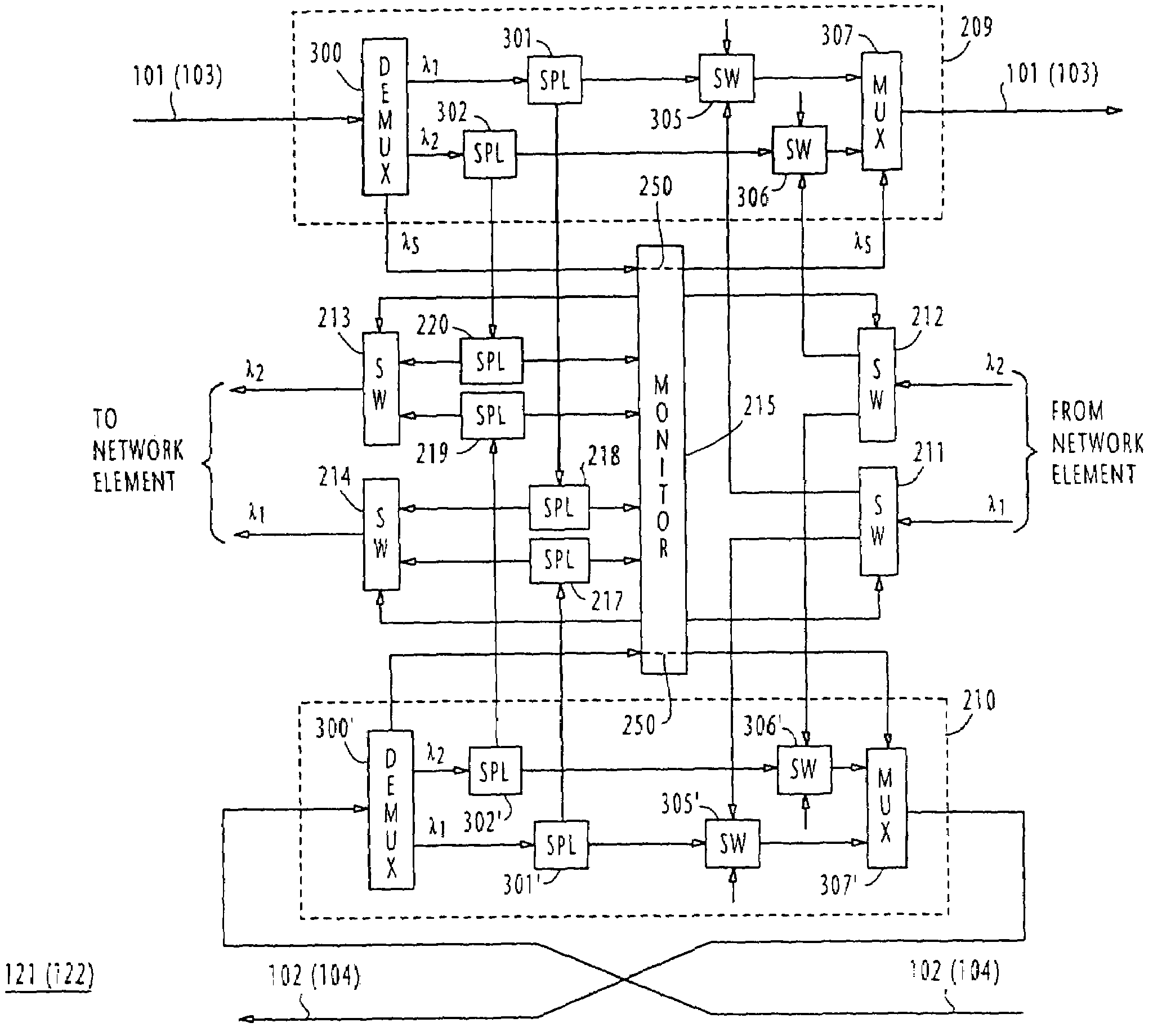
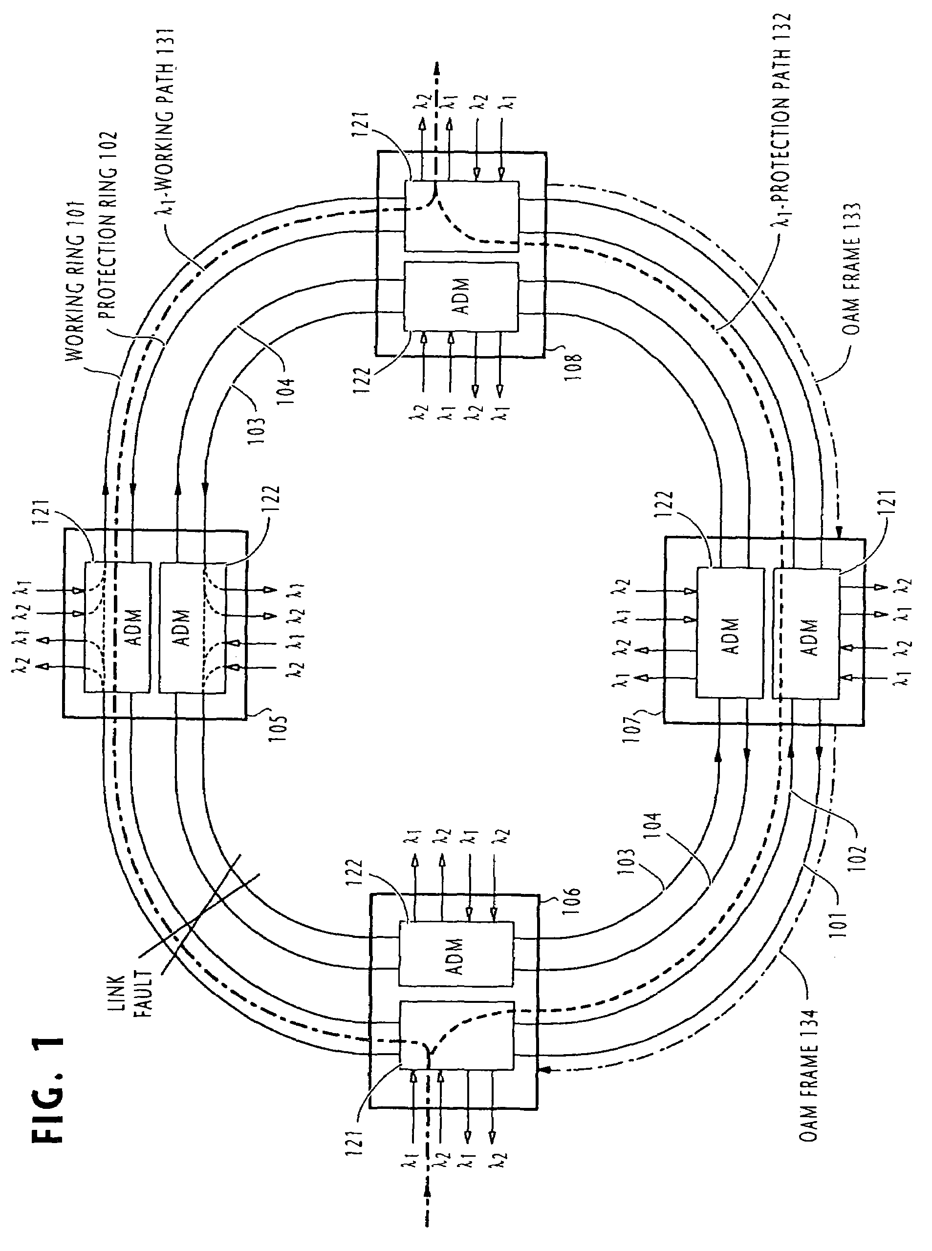
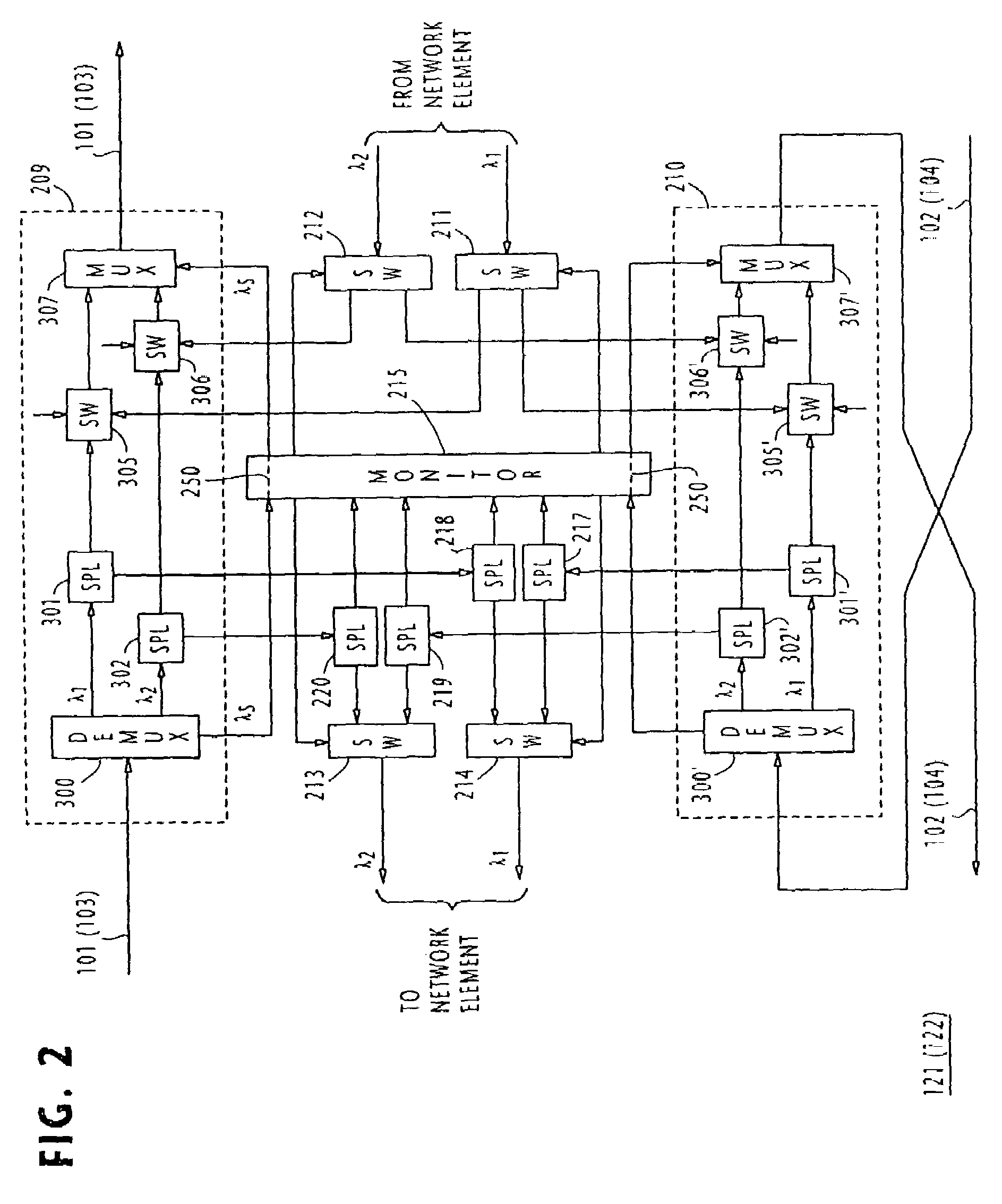
[0032]In FIG. 1, a wavelength-division multiplex (WDM) four-fiber ring network of the present invention is illustrated. The network is made up of a plurality of nodes 105 to 108 which interconnect optical fiber links to form rings 101 to 104 in a ring topology. Rings 101 and 102 form a first pair of working and protection transmission mediums, respectively, and the rings 103 and 104 form a second pair of working and protection transmission mediums, respectively. The directions of transmission of the working and protection rings of each pair are opposite to each other and the direction of transmission of the working ring of the first pair is opposite to that of the working ring of the second pair.

[0033]Each network node has a first add-drop optical multiplexer 121 for processing optical signals which normally propagate in the clockwise direction over the working ring 101 of the first pair and a second ADM 122 for processing optical signals which normally propagate in the counterclock...


PUM

PropertyMeasurementUnit
wavelengths λ1aaaaaaaaaa
wavelength λsaaaaaaaaaa
wavelengthsaaaaaaaaaa

Abstract

Multiple working paths are established on each working rings and multiple protection paths are established on each of multiple protection rings. A working path on a first working ring spans across first and second nodes for signal transmission in a first direction of the ring, and a working path on a second working ring spans across the first and second nodes for signal transmission in a second, opposite direction of the ring. A protection path on a first protection ring spans across the first and second nodes for signal transmission in said second direction, and a protection path on a second protection ring spans across the first and second nodes for signal transmission in said first direction. The first and second nodes normally use the working paths, respectively. When one of the working paths fails, the first and second nodes use a corresponding protection path.

Description

CROSS REFERENCE TO RELATED APPLICATION[0001]The present application is a divisional of U.S. patent application Ser. No. 09 / 200,583 filed on Nov. 27, 1998 now U.S. Pat. No 6,657,952.BACKGROUND OF THE INVENTION[0002]1. Field of the Invention[0003]The present invention relates generally to self-healing communications networks, and more specifically to a ring topology network which supports multiplex signals on protection communication paths during failures by fast switching from working communication paths.[0004]2. Description of the Related Art[0005]Ring topology networks, particularly, optical ring networks are currently receiving attention because of the number of wavelengths that can be multiplexed onto a single optical link is increasing due to recent innovative techniques. A number of technical publications deal with this topic. A four-fiber ring network is discussed in a technical paper “Multi wavelength Survivable Ring Network Architectures”, A. F. Elrefaie, Proceedings of ICC'...

Claims


Application Information

Patent Timeline
Patent Type & Authority Patents(United States)
IPC IPC(8): H04J3/04G01R31/08G02F1/00H04B10/08H04J14/00H04J14/02
CPCH04J14/0212H04J14/0297H04J14/0295H04J14/0283H04J14/0206
Inventor SHIRAGAKI, TATSUYAHENMI, NAOYANISHIO, MAKOTOTAKESHITA, HITOSHISHIMOMURA, HIROFUMI
Owner NEC CORP
Why Eureka
Try Eureka