Compressed air pumped hydro energy storage and distribution system

a compressed air and distribution system technology, applied in the direction of fluid couplings, clutches, engine components, etc., can solve the problems of less than 5% of the energy storage capacity of most countries, difficult new development, and the inability to simply drive an air motor generator with compressed air, etc., to achieve reliable, long-lasting use, and durable

Inactive Publication Date: 2007-10-16
EBO GROUP
View PDF3 Cites 115 Cited by
  • Summary
  • Abstract
  • Description
  • Claims
  • Application Information

AI Technical Summary

Benefits of technology

[0008]Another aspect of the invention is the provision of a compressed air pumped hydro energy system that improves the efficiency of previously known compressed air energy systems and pumped hydro energy systems, and which does so in a cost effective manner.
[0011]Still a further aspect of the invention is the provision of a compressed air pumped hydro energy system that is environmentally safe.
[0014]Yet another aspect of the invention is the provision of a compressed air pumped hydro energy system that is reliable, durable, and long lived in use.

Problems solved by technology

To date, pumped hydro systems have provided most of the world's electric energy storage, but the best of these resources have been tapped and environmental concerns make new development difficult.
Indeed, the electric energy storage capacity of most countries is less than 5% of their grid power capacity.
The compressed air cannot be used to simply drive an air motor generator due to the extreme cooling of the air as it expands through the turbine.
While the prior art has employed both pumped hydro and compressed air energy storage systems with some success, it appears that a combined system, capitalizing on the benefits of each, has not been envisioned.

Method used


Image

  • Compressed air pumped hydro energy storage and distribution system
  • Compressed air pumped hydro energy storage and distribution system
  • Compressed air pumped hydro energy storage and distribution system

Examples


Embodiment Construction

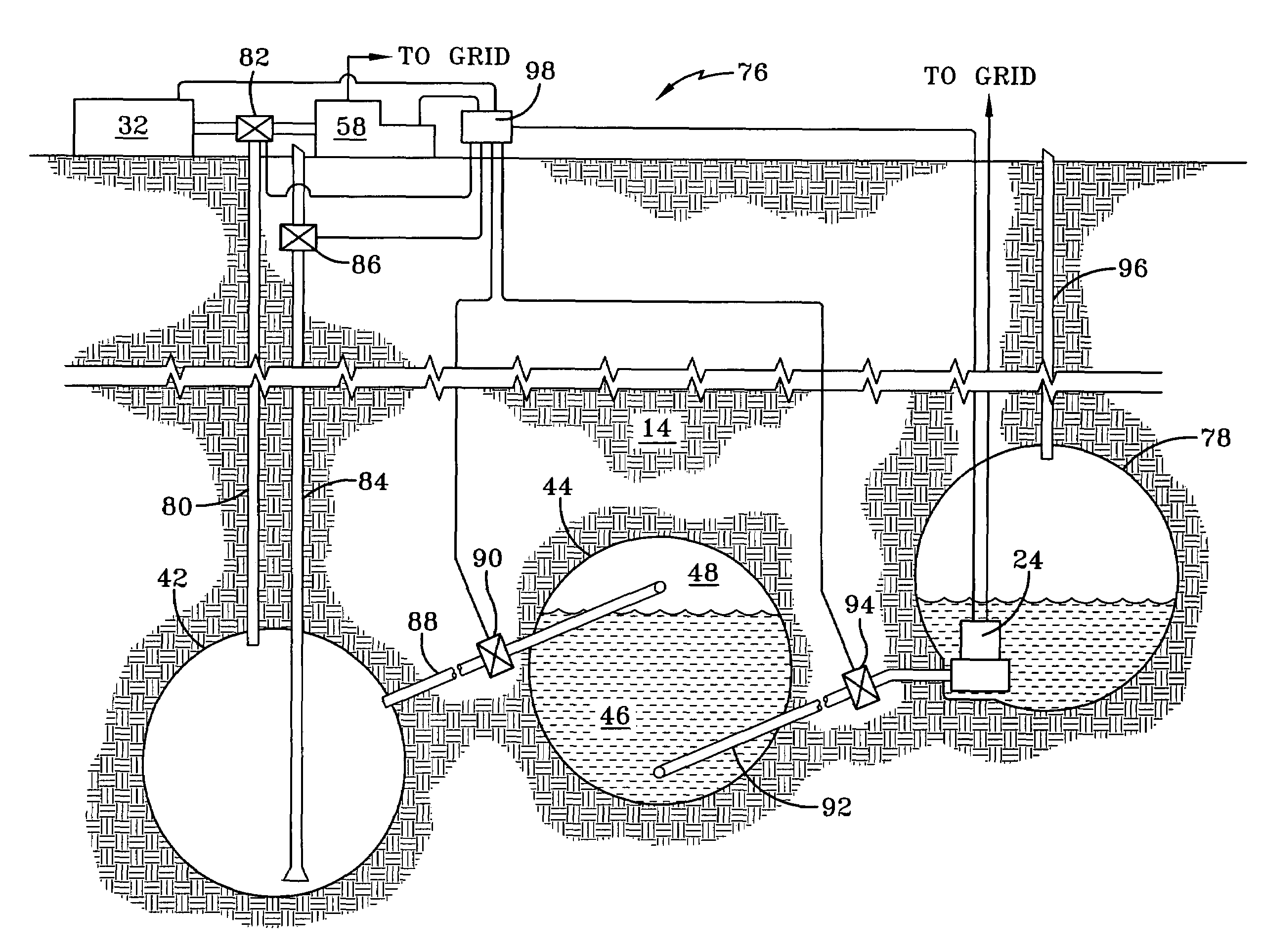
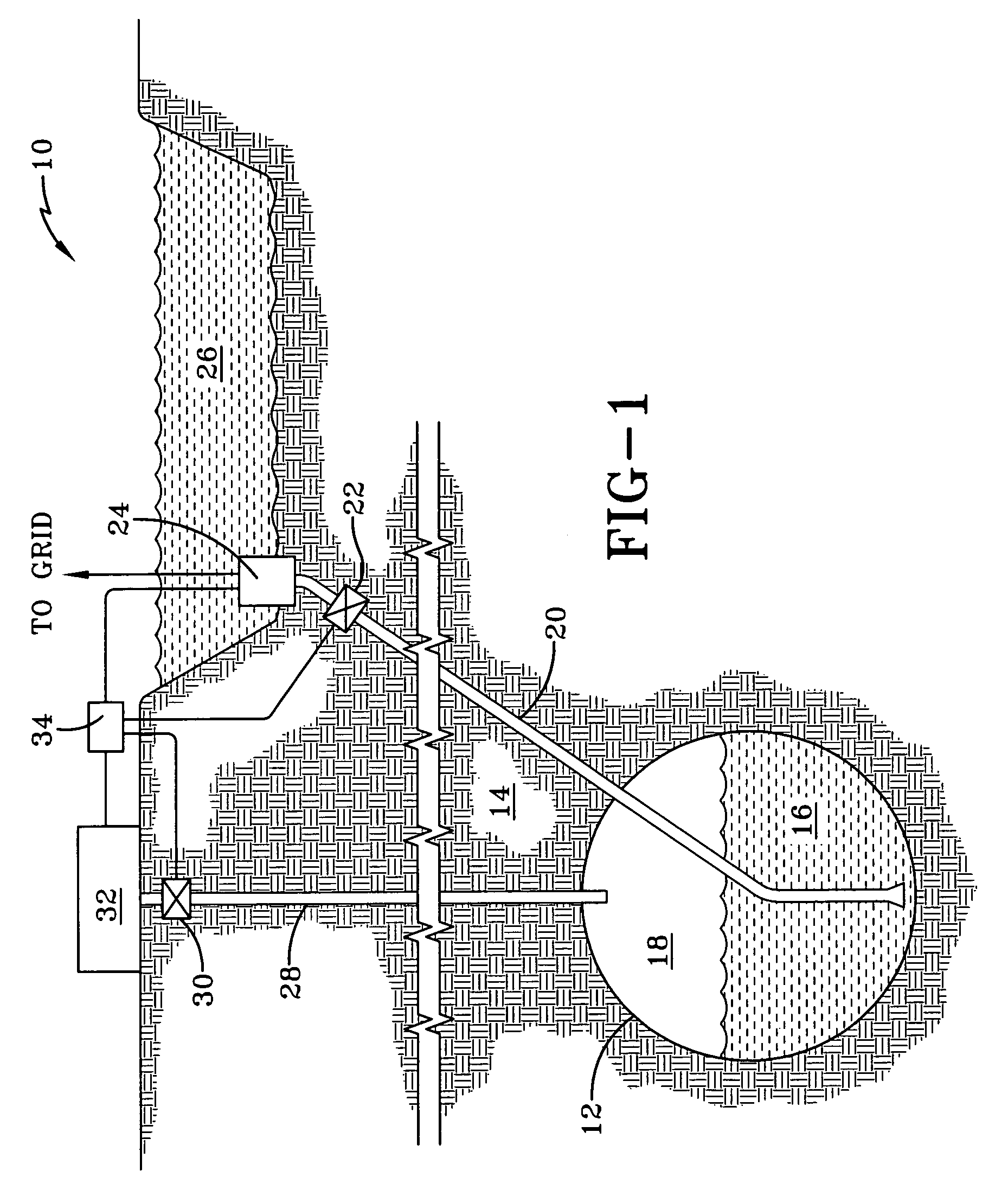
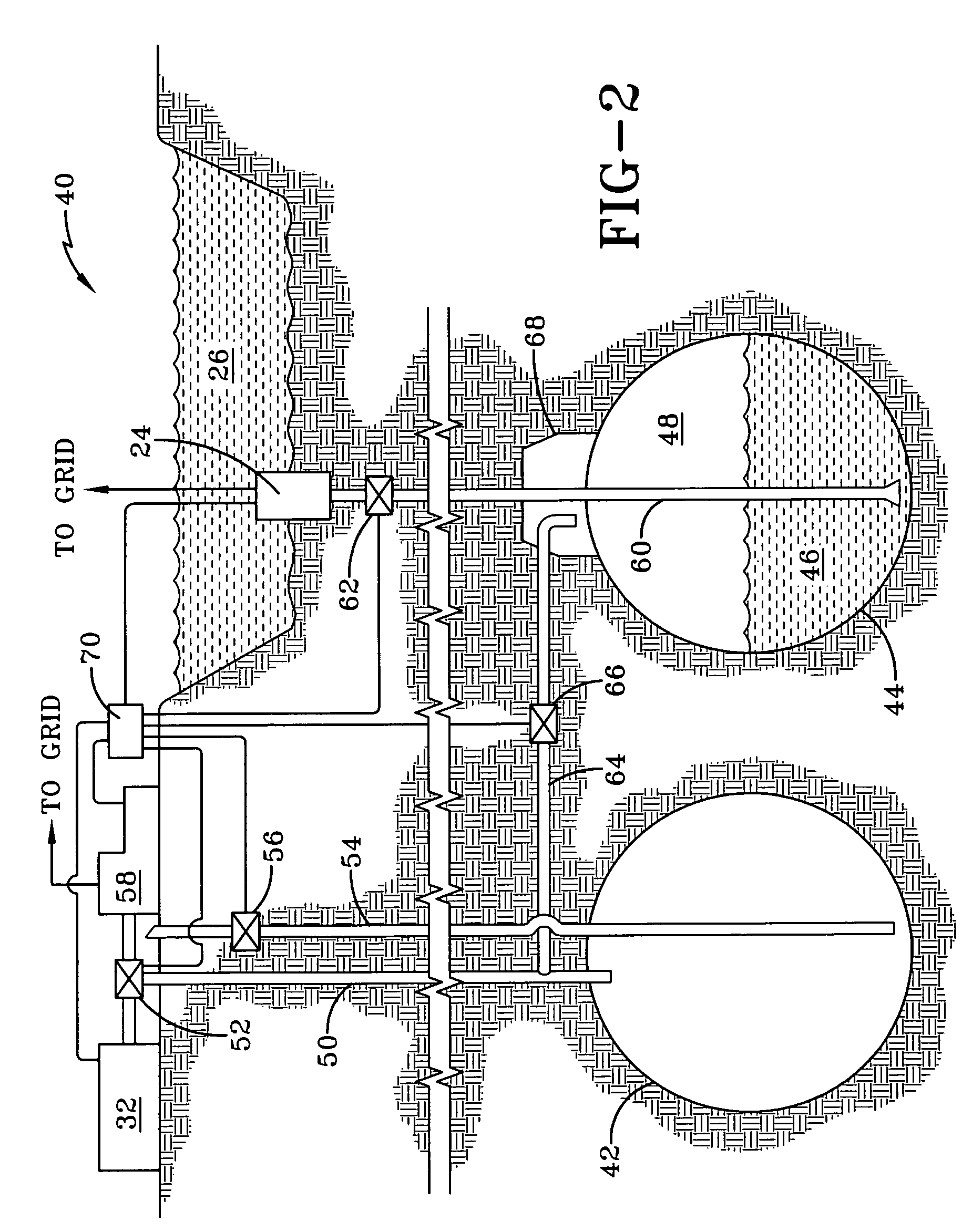
[0021]Referring now to the drawings and more particularly FIG. 1, it can be seen that a first embodiment of a compressed air pumped hydro energy system is designated generally by the numeral 10. As shown, the system 10 employs an appropriate cavity 12 within the earth 14 and below the surface thereof. It is contemplated that the cavity 12 would be an elongated cavity such as an abandoned mine or a tunnel excavated for this specific purpose. According to the invention, since the cavity 12 will be pressurized in use and contain water, the interior walls of the cavity 12 will typically be sealed by pressure grouting or the like. It is further contemplated that an appropriate membrane, such as an elastomeric member, might also be received within the cavity 12 and constrained by the walls thereof to provide the desired seal. The cavity or tunnel 12 has a lower portion 16, of varying capacity, that receives water, and an upper portion 18, receiving air. As will be appreciated, the volume ...


PUM


Abstract

A compressed air pumped hydro energy storage and distribution system includes a first reservoir of water and a second reservoir of air and water. An air pressure source, connected to the second reservoir, develops a pressure head in the second reservoir. A pump / turbine-motor / generator, received by the first reservoir, is connected to a regional energy grid. During peak demand periods, the pressure head forces water through the pump / turbine-motor / generator to generate power, delivered to the grid. During low demand periods, the pump / turbine-motor / generator pumps water back to the second reservoir, regenerating the pressure head. A third air reservoir interconnected with the second reservoir and a gas turbine generator can be used to generate power during peak demand periods. The reservoirs can be tunnels or abandoned mines, reinforced and sealed by pressure grouting and / or an internal liner, maintained well beneath the earth's surface and intersecting the path of the grid.

Description

TECHNICAL FIELD[0001]The invention herein resides in the art of power generation and energy storage and distribution and, more particularly, to systems employing compressed air or pumped water (hydro) as the energy storage and power generating medium. More particularly, the invention relates to a system combining the features of both compressed air and pumped hydro energy systems. More specifically, the invention relates to the provision of containment cavities or tunnels beneath the earth's surface, and in close proximity to a city or other region requiring energy, and in which the compressed air pumped hydro energy system is tied to the energy grid of the city or region.BACKGROUND ART[0002]The electric power grid systems in developed countries have a growing need for energy storage, especially as wind and solar power provide an increasing portion of energy requirements. To date, pumped hydro systems have provided most of the world's electric energy storage, but the best of these r...

Claims


Application Information

Patent Timeline
Patent Type & Authority Patents(United States)
IPC IPC(8): F16D31/02
CPCF03B13/00F03B13/06Y02E10/20Y02E60/16
Inventor HEIDENREICH, DAVID C.
Owner EBO GROUP
Why Eureka
Try Eureka