Surge control system for a compressor

a compressor and control system technology, applied in the field of compressor control systems, can solve the problems of damage to the engine or its intake pipe system, severe aerodynamic fluctuations, and significant flow separation on the blades

Inactive Publication Date: 2007-10-16
GARRETT TRANSPORATION I INC
View PDF12 Cites 23 Cited by
  • Summary
  • Abstract
  • Description
  • Claims
  • Application Information

AI Technical Summary

Benefits of technology

[0044]Surge control by the present invention has many advantages. For instance, FIG. 11 illustrates the expansion of the working area of the compressor 11 when the surge control system 10 of the present invention is used. The working envelope without compressed air recirculation is defined by a solid line 200. The solid line 202 defines the compressor operating line without exhaust gas recirculation. The dashed line 203 represents how the operating line is shifted with exhaust gas recirculation. It can be seen that the operating line at low air flow conditions is into the surge area of the map. The dotted line 201 shows how the operating envelope is expanded by compressed air recirculation in accordance with the invention; as a result, even with exhaust gas recirculation, the operating line 203 falls within the non-surge region of the map. Expansion of the operating range of the compressor system is enhanced through cooling of the recirculated air and / or mixing of the recirculated air with the intake air such that substantially uniform flow conditions exist at the entrance to the compressor. Without adequate mixing, non-uniform flow conditions would tend to hurt compressor efficiency.

Problems solved by technology

Generally, surge occurs when the compressor is driven into low-flow, high pressure-ratio conditions, the result of which is that the compressor blades are forced to operate at such high incidence angles that significant flow separation occurs on the blades.
Surge can result in severe aerodynamic fluctuations within the compressor of the turbocharger and can even cause damage to the engine or its intake pipe system.
In one instance, surge can occur when compressor exhaust gas recirculation flow is relatively high at low engine speed.
In another instance, sudden deceleration of the engine due to closing of the throttle valve can result in surge.

Method used


Image

  • Surge control system for a compressor
  • Surge control system for a compressor
  • Surge control system for a compressor

Examples


Embodiment Construction

[0021]The present inventions now will be described more fully hereinafter with reference to the accompanying drawings, in which some, but not all embodiments of the invention are shown. Indeed, the invention may be embodied in many different forms and should not be construed as limited to the embodiments set forth herein; rather, these embodiments are provided so that this disclosure will satisfy applicable legal requirements. Like numbers refer to like elements throughout.

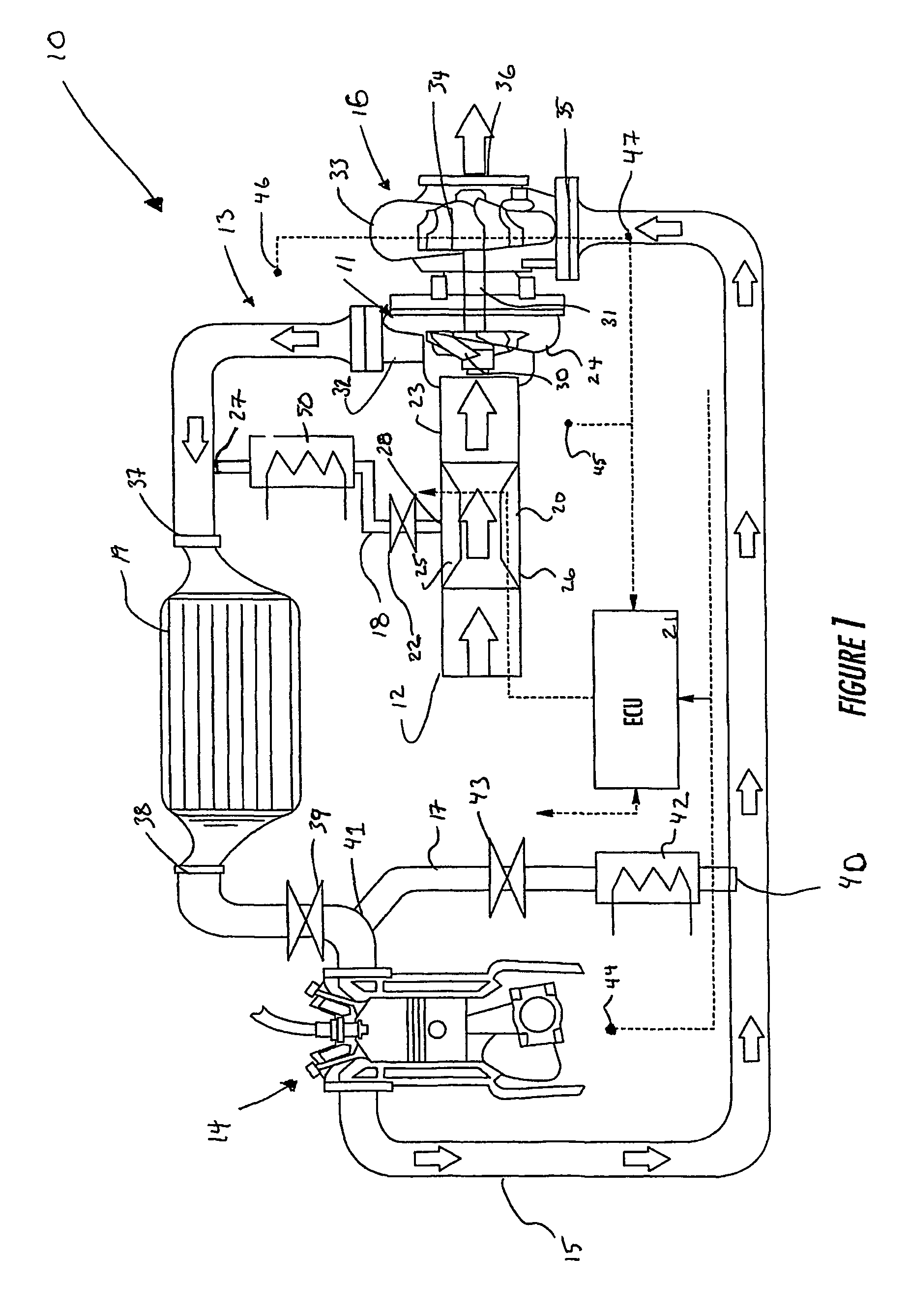
[0022]A compressor active surge control system 10 of one embodiment of the present invention, as shown in FIG. 1, includes a compressor 11, a compressor inlet line 12, a compressor discharge line 13, a recirculation line 18 connecting the inlet and discharge lines, an air cooler 50 and an air mixer 20. Generally, the compressor 11 supplies compressed air through the line 13 to a combustion engine 14 so as to increase power output by the engine. An exhaust gas line 15 conducts exhaust from the engine 14 to a turbin...


PUM


Abstract

A compressor active surge control system that includes an air recirculation line that has a first end connected downstream of a compressor outlet and a second end connected upstream of a compressor inlet. The gas recirculation line recirculates compressed air from the compressor outlet to the compressor inlet. Also included in the system is a mixer positioned to receive both ambient air and recirculated air. Mixing of the air homogenizes the air prior to its introduction into the compressor. An air cooler may be included that cools the recirculated air prior to its introduction into the compressor. Cooling and mixing of the recirculated air expands the operating range of the compressor by reducing the incidence of surge. Various existing components, such as intercoolers and filters, may serve the additional duty of cooling or mixing the recirculated air.

Description

BACKGROUND OF THE INVENTION[0001]1. Field of the Invention[0002]The present invention is related to the use of compressor systems (e.g., turbochargers) for boosting the power output of combustion engines, and in particular to the use of recirculated compressor discharge air to facilitate the operation of such compressors.[0003]2. Description of Related Art[0004]Vehicle engine turbochargers provide an advantageous boost to engine power, especially at higher engine speeds. A turbocharger uses the exhaust gasses from an engine to drive a turbine that drives a compressor, which, in turn, increases the pressure of the engine intake air. The compressed engine intake air results in the boost of engine power. In some turbocharger engine systems, a portion of the exhaust gases from the engine is recirculated back to the intake of the engine to control emissions. In other systems, the compressor drive may be electrically assisted or the turbine may include a variable geometry nozzle to furthe...

Claims


Application Information

Patent Timeline
Patent Type & Authority Patents(United States)
IPC IPC(8): F02B29/04F02B37/12F02B37/16F02B39/16F02D9/02F02M25/07F02M35/024
CPCF02B29/0412F02B37/12F02B37/16F02B39/16F02M25/0707F02M35/024F02D2009/0237Y02T10/144F02M25/0727Y02T10/121Y02T10/146F02D2009/0249F02M26/05F02M26/23Y02T10/12
Inventor GU, RONGLEIFUJIKAWA, YASUOWATANABE, YOSHIKIYOISHII, ATSUSHI
Owner GARRETT TRANSPORATION I INC
Why Eureka
Try Eureka