Stemless hemispherical resonator gyroscope

Inactive Publication Date: 2007-10-16
INNALABS
View PDF5 Cites 33 Cited by
  • Summary
  • Abstract
  • Description
  • Claims
  • Application Information

AI Technical Summary

Benefits of technology

[0014]The present invention relates to an improved high precision stemless hemispherical reson

Problems solved by technology

The design of the gyroscope that uses a hemispherical resonator, as described above, suffers from a number of problems.
One of these problems is the difficulty in mass-producing a relatively complex-shaped part—the meniscus-shaped resonator with a stem, which is used for mounting.
Such a shape is relatively difficult to produce in mass quantities.
Another problem is that due to the complex shape, maintaining perfect axial symmetry of the resonator is extremely difficult.
This raises the cost of the resonator considerably, and increases the manufacturing time.
Another difficulty with such convention

Method used


Image

  • Stemless hemispherical resonator gyroscope
  • Stemless hemispherical resonator gyroscope
  • Stemless hemispherical resonator gyroscope

Examples

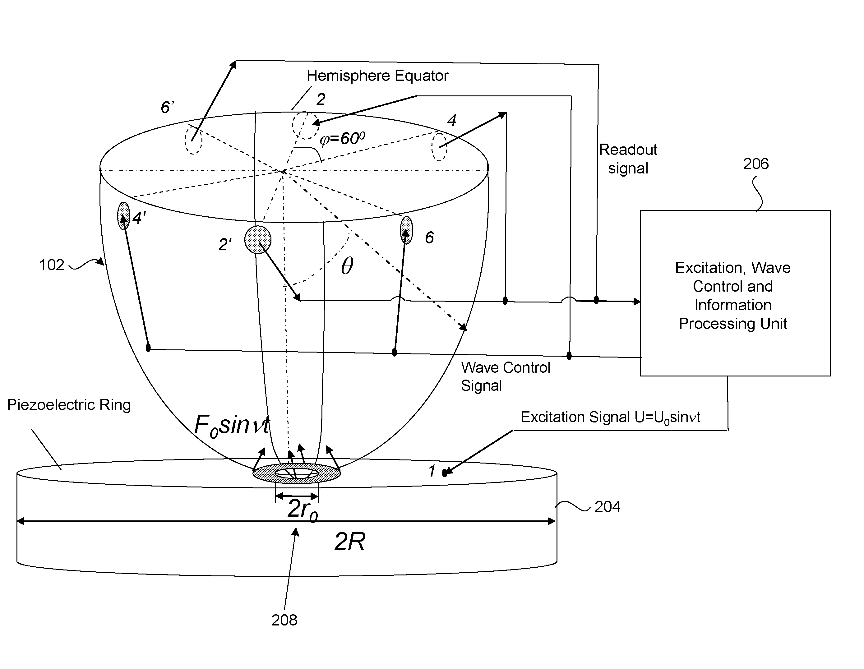
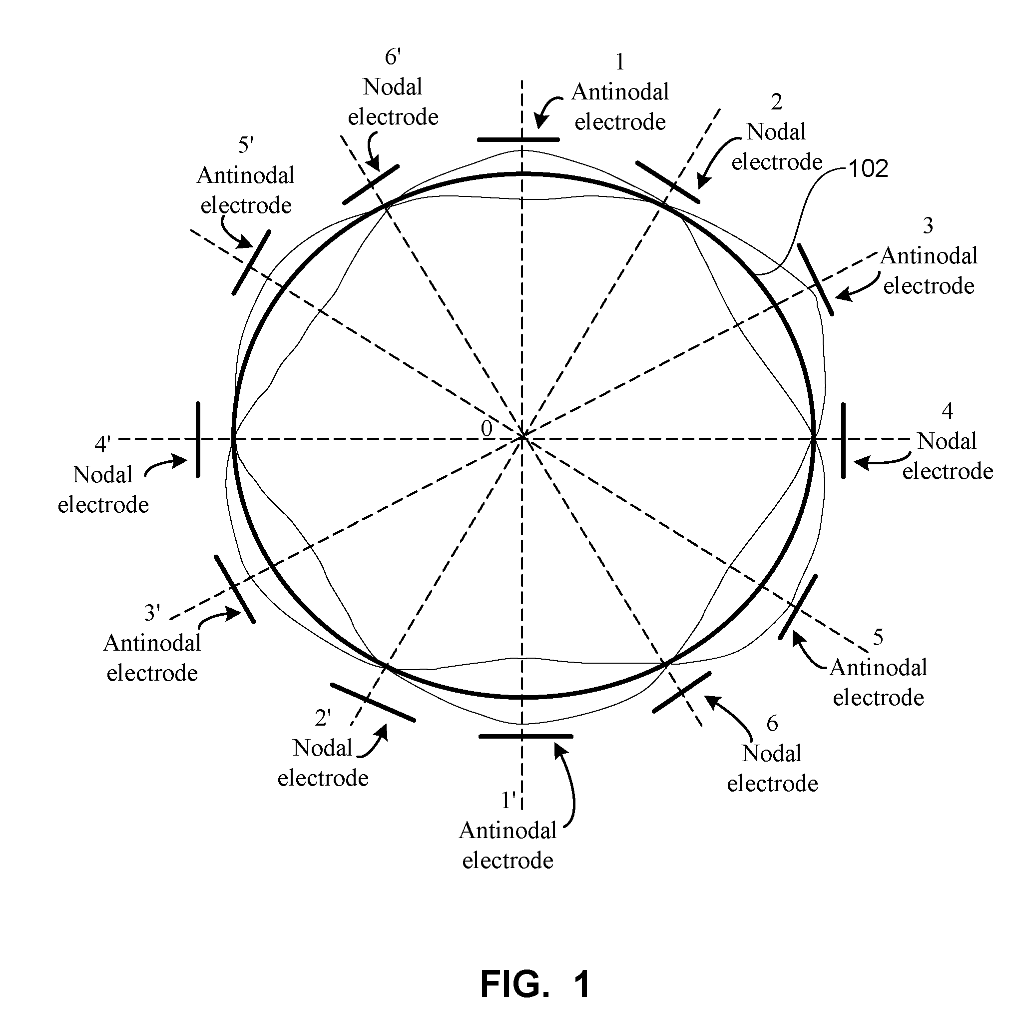
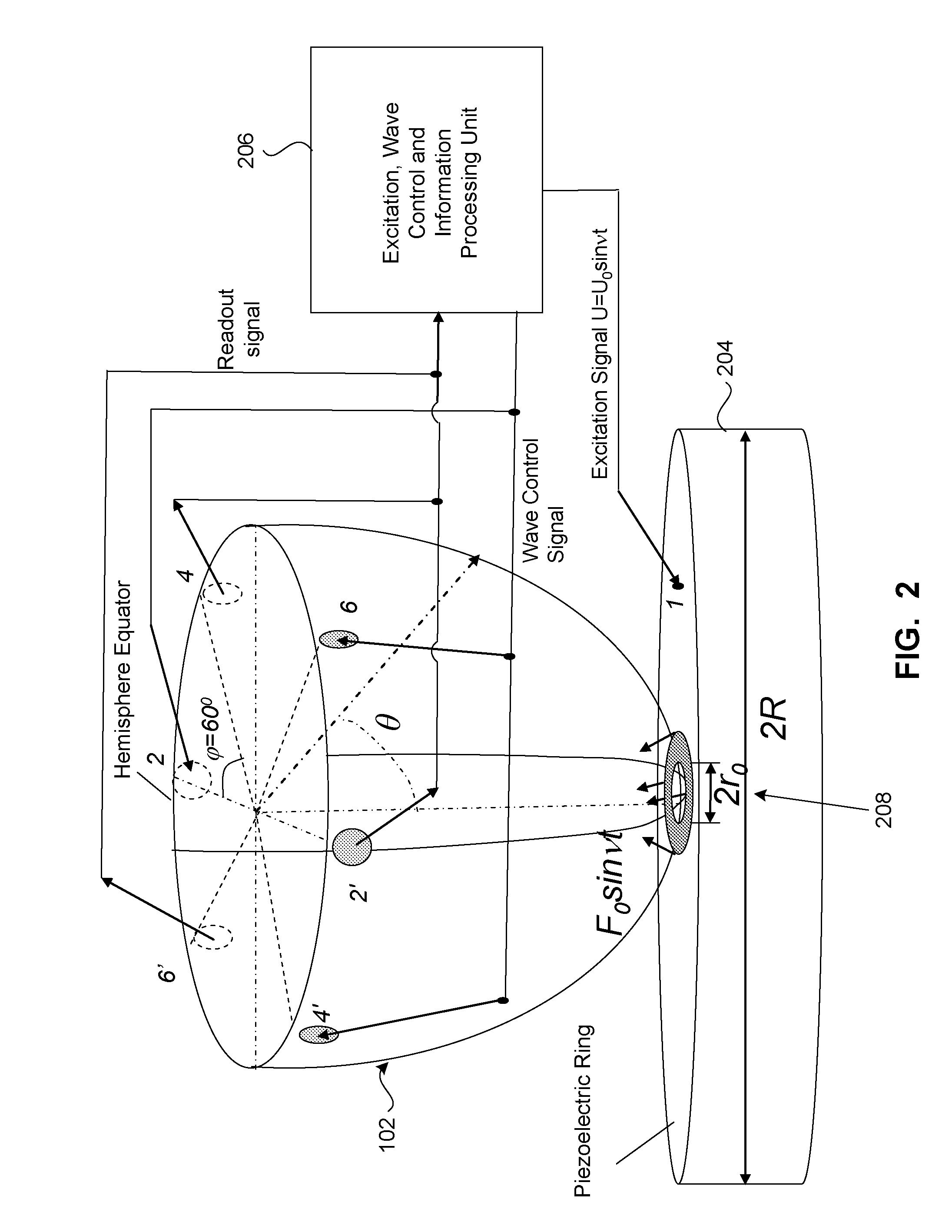

Embodiment Construction

[0029]Reference will now be made in detail to embodiments of the present invention, examples of which are illustrated in the accompanying drawings.

[0030]One embodiment of the present invention is a vibrational gyroscope with a hemispherical resonator that is stemless. The hemisphere is mounted on a piezoelectric ring, for example, using glue or epoxy. The ring itself can be manufactured from any material that has piezoelectric properties. The pole of the hemisphere is positioned directly over the opening of the piezoelectric ring. At the same time, the piezoelectric ring can be unitary, or can be segmented using a segmented coating (for example, silver), depending on which vibration mode is chosen, for example, second, third, etc. In the case of a segmented ring, each segment of the ring receives a voltage to excite the resonator and / or (in the case of closed-loop operation) to control the standing wave, and, also possibly to read out the signal that relates to the angular velocity....


PUM


Abstract

A vibrational gyroscope includes a piezoelectric ring having a central opening, and a hemispherical resonator having a central opening and mounted over the opening of the central opening of the piezoelectric ring. A plurality of electrodes delivers a voltage to the piezoelectric ring. A plurality of electrodes provides signal readout that corresponds to angular velocity. The hemispherical resonator can be glued to the piezoelectric ring. The hemispherical resonator preferably vibrates in the third vibration mode. A plurality of capacitive electrodes can be located at nodes and at antinodes of the vibration of the hemispherical resonator, and provide a signal readout that corresponds to the angular velocity. The piezoelectric ring is segmented, non-segmented, or includes an outer segmented portion and an inner non-segmented portion. The inner non-segmented portion can be used to excite the resonator into a vibration mode, and the outer segmented portion provides a readout signal and is used to adjust the vibration of the resonator. The piezoelectric ring includes a conductive coating used to conduct excitation voltage to the piezoelectric ring.

Description

BACKGROUND OF THE INVENTION[0001]1. Field of the Invention[0002]The present invention relates to vibrational gyroscopes, and more particularly, to high performance stemless hemispherical resonator gyroscopes.[0003]2. Background Art[0004]Generally, the present invention is related to coriolis vibration gyroscopes (CVGs) that typically use resonators made of quartz. Such gyroscopes are described, for example, in U.S. Pat. Nos. 4,951,508, 4,157,041, 3,719,074, 3,656,354, 6,357,296 and 5,383,362.[0005]Numerous geometries of vibrational structures are known, and these various geometries are commonly used in vibrational gyroscopes. For example, such structures include disks, rods, cylinders, hemispheres, etc. The vibrating elements can be made out of different materials, such as ceramics, glass, quartz, metal, although the use of quartz or fused silica is most common. Usually, the best performance is provided by gyroscopes whose resonators have a high degree of axial symmetry, and the res...

Claims


Application Information

Patent Timeline
IPC IPC(8): G01P9/04
CPCG01C19/5691
Inventor CHIKOVANI, VALERY V.YATZENKO, YURY A.KOVALENKO, VLADIMIR A.SCHERBAN, VLADIMIR I.
Owner INNALABS
Why Eureka
Try Eureka