Loading/unloading device for shelving

a technology for shelving and loading/unloading, which is applied in the direction of computer control, instruments, etc., can solve the problems of increased braking distance between bottom and top traction drives, and the risk of rack and pinion drives being forced due to misalignment of masts, etc., to achieve increased rigidity and load-bearing capacity of masts, the effect of high running accuracy

Inactive Publication Date: 2007-10-16
TGW MECHANICS GMBH
View PDF22 Cites 30 Cited by
  • Summary
  • Abstract
  • Description
  • Claims
  • Application Information

AI Technical Summary

Benefits of technology

[0038]The U-shaped protuberances provided in the stiffening elements as described in claims 52 to 60 further increase the rigidity and load-bearing capacity of the mast because the forces transmitted by the load-bearing wheels onto the running surfaces of the protuberances are not only absorbed by the section strips but also by the stiffening elements in the regions adjoining the protuberances, so that the guide tracks standing proud of the side of the mast enable a high running accuracy for the lifting mechanism and the load-bearing means throughout the entire operating time.
[0039]Finally, however, the embodiment defined in claim 61 is also of advantage because the mast is able to absorb forces throughout its entire cross section and is a lightweight construction.

Problems solved by technology

The disadvantage of this rack serving device is the risk of the rack and pinion drive being forced due to misalignment of the mast if the electric synchronisation fails.
The uneven moment of inertia of the mast foot and mast head depending on the position of the lift carriage means that greater differences in the braking path between bottom and top traction drives can be expected, and hence misalignment of the mast.
In the case of this particular rack serving device, this causes a strong pressure on the sides of the meshing teeth of the rack and pinion drive, which can lead to damage.
The disadvantage of this rack serving device is the highly complex mechanical system needed for the connecting shaft and its mounting on the mast, as well as the very high costs incurred by the top and bottom gear rack and their accurate laying in the aisle of the racking system.
Furthermore, this rack serving device is susceptible to barely controllable vibrations under dynamic load because the extremely long connecting shaft is very easily twisted and acts like a torsion spring under dynamic influences.
The rack serving devices above known from patent specifications DE 44 05 052 A1, EP 0 621 231 A1, CH 518 862 and CH 518 863 also have problems in terms of noise, lubrication and wear due to the open construction of the teeth and the relatively high cost of the materials, assembly and maintenance.
The high build-up of noise also means that the rack serving devices described above can be used on a limited basis only.
The various disadvantages outlined above are so serious that these rack serving devices have not been able to gain a foothold on the market to date.
The disadvantage of this is that the drive rollers are disposed and roll on oppositely lying guide rails of the web and also serve as lateral guide members for the bogie assembly frame incorporating the drive.
If a mast of a rack serving device of this type is fitted with a bogie assembly driven in this manner at its mast foot and mast head and the mast moves out of line from its vertical orientation and / or is subjected to forces acting in the transverse direction to the aisle, the drive rollers will be subjected to increased friction-induced wear, which means that these bogie assemblies can only be used on rack serving devices of a small construction and operated at low displacement speeds.
For this reason alone, the range of applications for which rack serving devices fitted with these bogie assemblies can be used is severely limited and they could not be used, or could be used under limited conditions only, for modern order picking systems where travel speeds of up to 7 m / sec and mast heights of up to 20 m as well as low maintenance are required.
The deformation occurring caused in the mast during operation alone causes stress on the drive rollers and the increased friction-induced wear mentioned above.
The disadvantage of rack serving devices of this type is that the driveable wheels are designed to transmit a forward motion to the bogie assembly in the direction of the aisle on the one hand and to take the natural weight of the mast and the load to be carried on the other, which means that high friction forces occur between the load-bearing wheels and the bottom rail, especially when subjected to high loads, and the requisite driving torque of the drive motor has to be significantly increased in equal measure, adding extra costs to the production of the rack serving device and requiring more space in view of the more robust motors needed for the bogie assembly.

Method used


Image

  • Loading/unloading device for shelving
  • Loading/unloading device for shelving
  • Loading/unloading device for shelving

Examples


Embodiment Construction

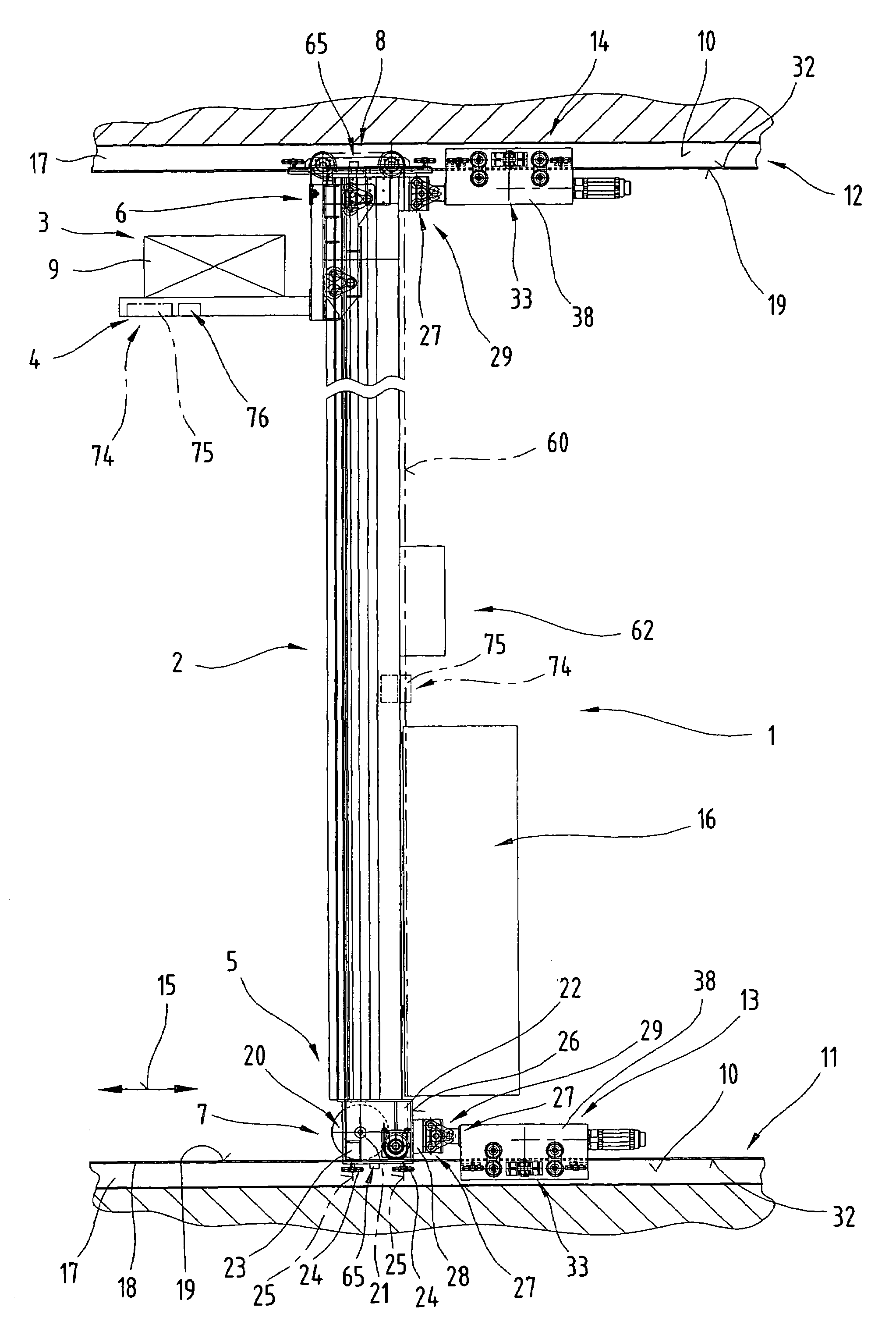
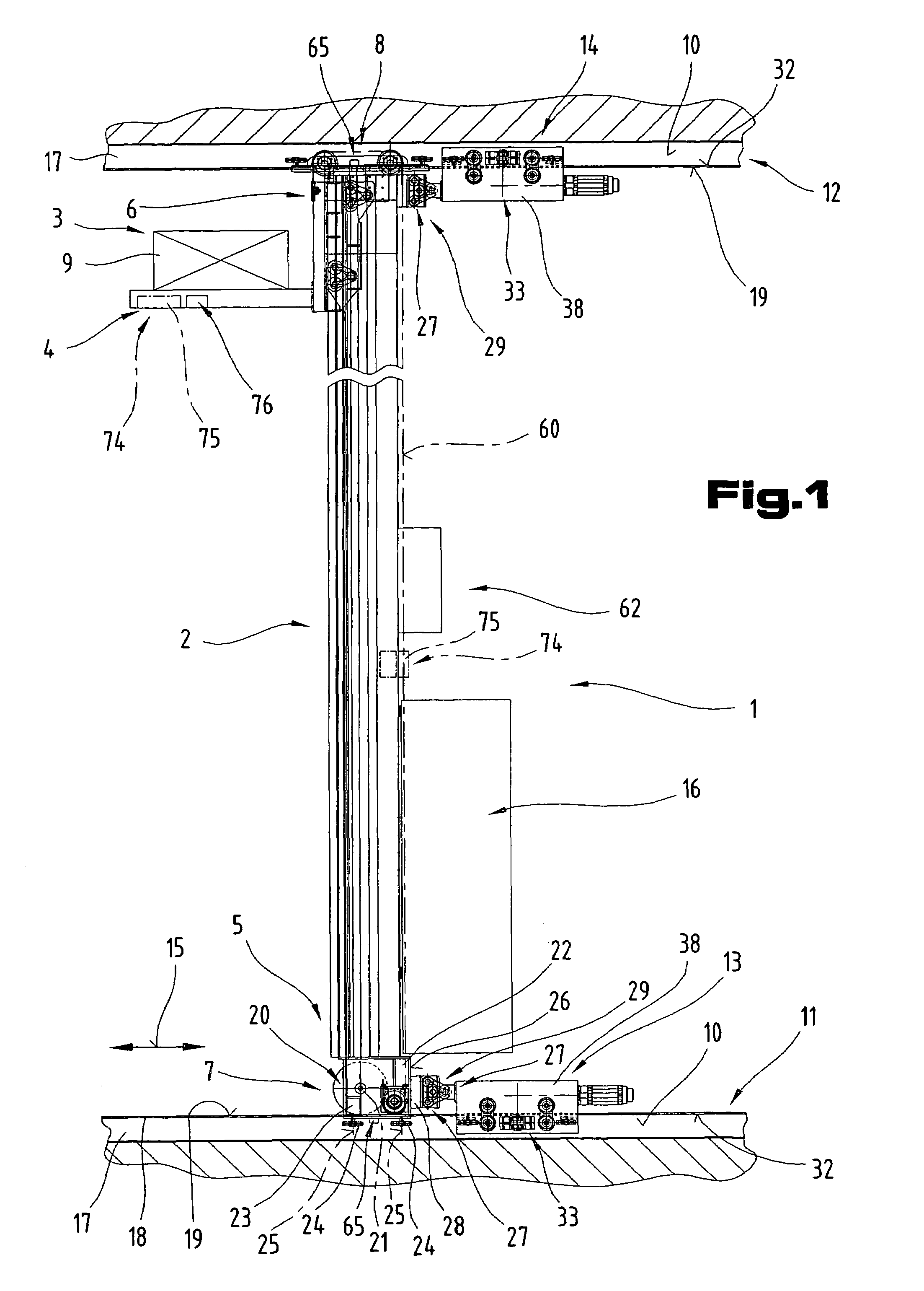
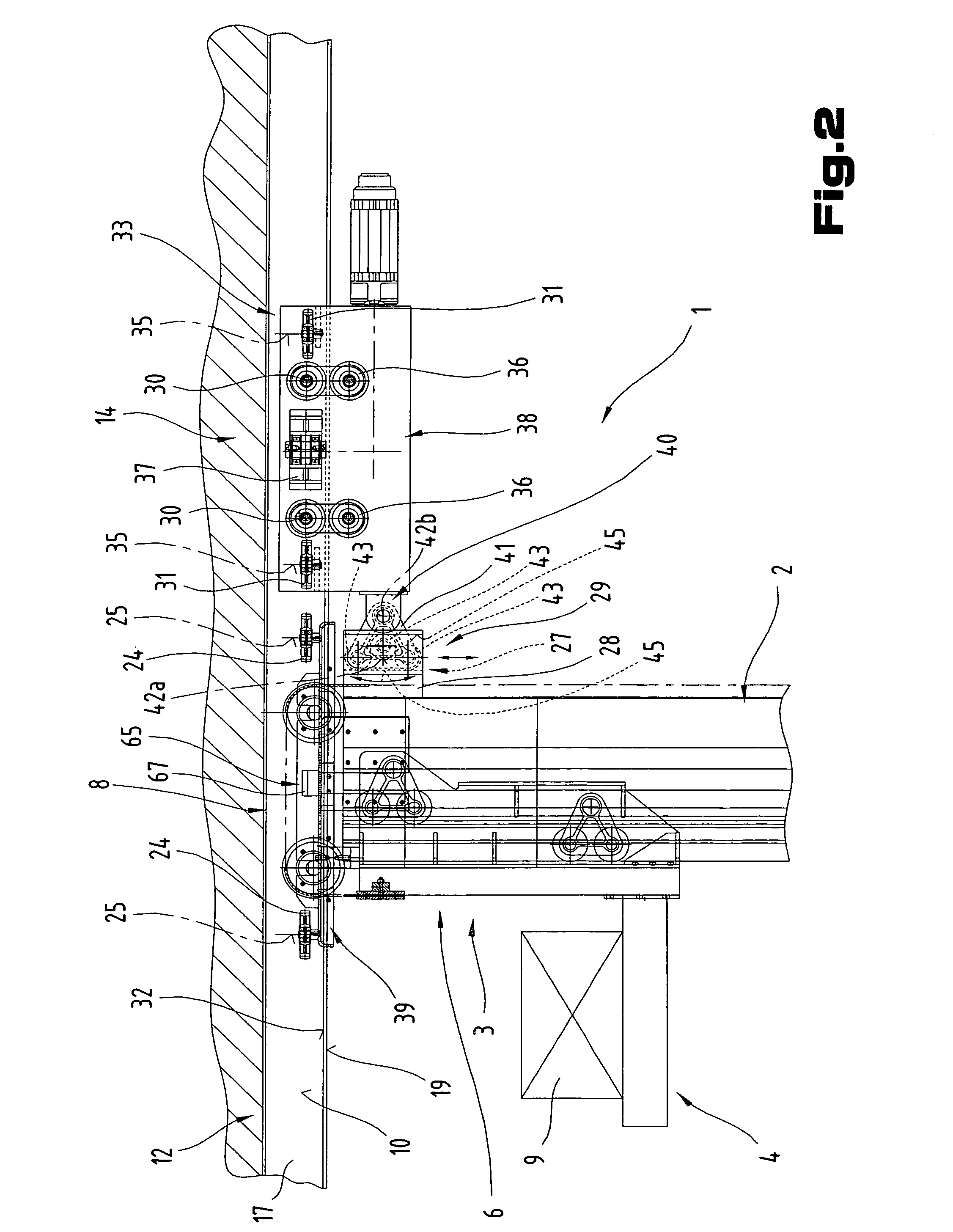
[0054]Firstly, it should be pointed out that the same parts described in the different embodiments are denoted by the same reference numbers and the same component names and the disclosures made throughout the description can be transposed in terms of meaning to same parts bearing the same reference numbers or same component names. Furthermore, the positions chosen for the purposes of the description, such as top, bottom, side, etc, relate to the drawing specifically being described and can be transposed in terms of meaning to a new position when another position is being described. Individual features or combinations of features from the different embodiments illustrated and described may be construed as independent inventive solutions or solutions proposed by the invention in their own right. It should be pointed out from the outset that the rack serving device 1 proposed by the invention is suitable for travelling in straight lines only.

[0055]FIGS. 1 to 3, which will be described...


PUM


Abstract

The invention relates to a rack serving device (1) with a load-bearing means (4) displaceable in the height direction of a mast (2), the mast (2) being guided by means of bogie assemblies (7, 8) on bottom and top guide tracks and mounted so as to be displaceable along the guide tracks by means of a bottom and top friction-locking displacement drive (13, 14). The bottom and the top adjusting mechanisms are guided by means of height and lateral guide elements on the guide track and are designed to be displaceable relative to the guide tracks by means of a drive system (33). Arranged respectively between the displacement drives (13, 14) and bogie assemblies (7, 8) is a coupling mechanism (29), comprising at least two displaceable coupling parts (28) and, extending between the articulation axes of the coupling parts (28), at least one coupling connection (27) which is pivotable about the articulation axis substantially perpendicular to the longitudinal extension of the guide track relative to a coupling part (28) and, at an end region remote from this articulation axis, mounted so as to be slideable in a longitudinal guide extending substantially parallel with the longitudinal extension of the mast (2).

Description

CROSS REFERENCE TO RELATED APPLICATIONS[0001]Applicants claim priority under 35 U.S.C. §119 of AUSTRIAN Application No. A 925 / 2001 filed on Jun. 13, 2001 and AUSTRIAN Application No. A 575 / 2002 filed on Apr. 12, 2002. Applicants also claim priority under 35 U.S.C. §365 of PCT / AT02 / 00164 filed on May 29, 2002. The international application under PCT article 21(2)was not published in English.BACKGROUND OF THE INVENTION[0002]1. Field of the Invention[0003]The invention relates to a rack serving device with a lift carriage.[0004]2. Description of the Related Art[0005]A number of different rack serving devices are known, which essentially differ in terms of the layout of the drives and the structural design of the mast, namely depending on whether they are single-mast or twin-mast systems.[0006]Patent specification DE 44 05 952 A1 describes a rack serving device, which is displaced by means of top and bottom drives, the travel of which is controlled in synchronisation. The rack serving d...

Claims


Application Information

Patent Timeline
Patent Type & Authority Patents(United States)
IPC IPC(8): B65G1/04B66C19/00B66F9/07
CPCB65G1/0407B66F9/072B66F9/07
Inventor HANSL, RUDOLFSCHWINGSHANDL, THOMASENSINGER, WOLFGANGASCHAUER, HERBERT
Owner TGW MECHANICS GMBH
Why Eureka
Try Eureka