Power generating wind turbine

a technology of power generation wind turbine and wind power, which is applied in the direction of bearing unit rigid support, electric generator control, gearbox, etc., can solve the problems of nacelle and tower supporting the nacelle, the nacelle is too large, the size gearbox is inevitably made larger, etc., to achieve the effect of small size, light weight, and reduced weigh

Active Publication Date: 2007-10-16
MITSUBISHI HEAVY IND LTD
View PDF39 Cites 33 Cited by
  • Summary
  • Abstract
  • Description
  • Claims
  • Application Information

AI Technical Summary

Benefits of technology

[0015]In view of the problems in the prior art, it is an object of the present invention to provide a power generating wind turbine in which parts and components provided in the nacelle can be made compact in size and light in weight and the maintenance can be facilitated.

Problems solved by technology

That is, even if a speed-up ratio is the same, a gear-box for which a higher strength is required is inevitably made larger to that extent.
Such a large size gear-box has a heavy weight and hence the load adding to the gear-box, nacelle and tower supporting the nacelle also becomes large.
Thus, these parts and components are required to have a higher strength, and this results in these parts and components having a large size and heavy weight.
In the prior art power generating wind turbine, therefore, there are problems not only in the manufacturing cost but also in the transportation and installation work of each of the constructional parts and components, such as the gear-box, nacelle, tower or the like.
Moreover, by using such a large size gear-box, a space in the nacelle becomes narrower and the freedom of structure of the nacelle and the freedom of arrangement of the parts and components installed in the nacelle become smaller so that the design becomes difficult.
Thus, the maintenance work becomes very troublesome.

Method used


Image

  • Power generating wind turbine
  • Power generating wind turbine
  • Power generating wind turbine

Examples


first embodiment

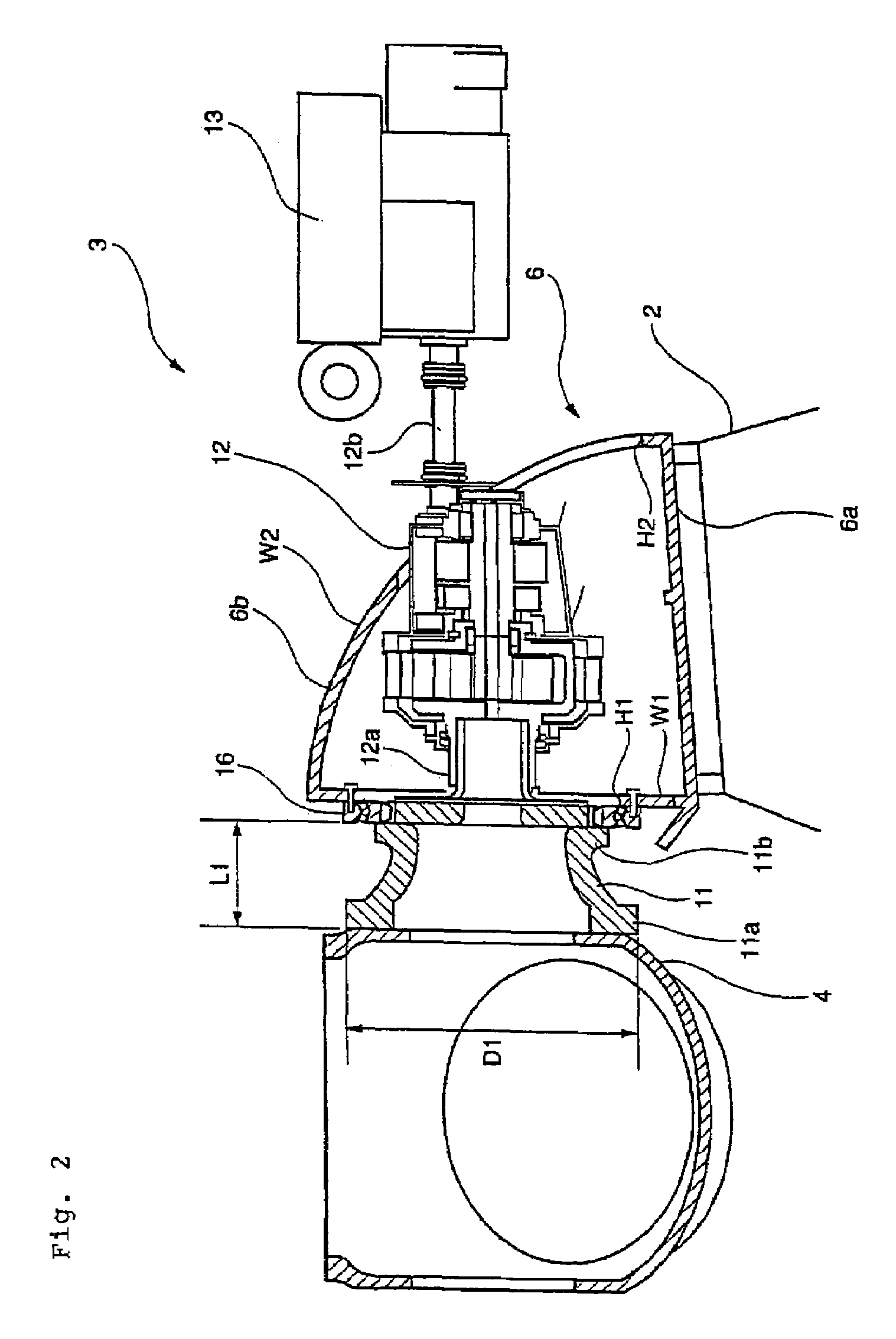
[0051]A first embodiment according to the present invention will be described with reference to FIGS. 1 to 3.

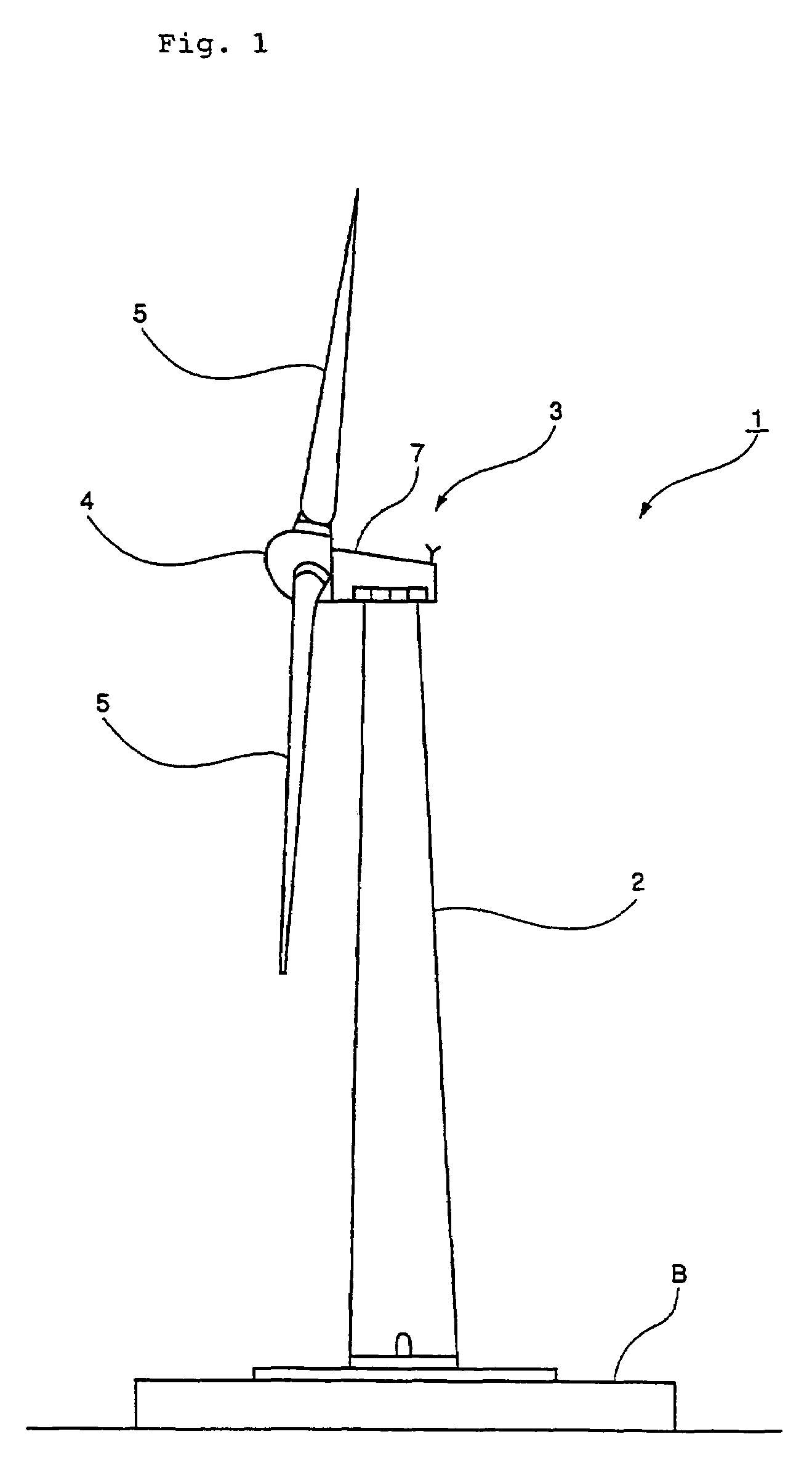
[0052]A power generating wind turbine 1 of the present embodiment, as shown in FIG. 1, comprises a tower 2 provided to rise on a base B, a nacelle 3 provided on an upper end of the tower 2 and a rotor head 4 provided onto the nacelle 3 so as to be rotatable around a substantially horizontal axis. A plurality of wind turbine rotating blades 5, arranged radially around a rotational axis of the rotor head 4, are fitted to the rotor head 4, so that a wind force working on the wind turbine rotating blades 5 from a rotating axis direction of the rotor head 4 is converted into power to rotate the rotor head 4 around the rotational axis thereof.

[0053]The tower 2 is constructed, for example, by a plurality of tower components being vertically piled one on another. The nacelle 3 is installed on the uppermost one of the tower components constituting the tower 2. The nacelle 3 comprises ...

second embodiment

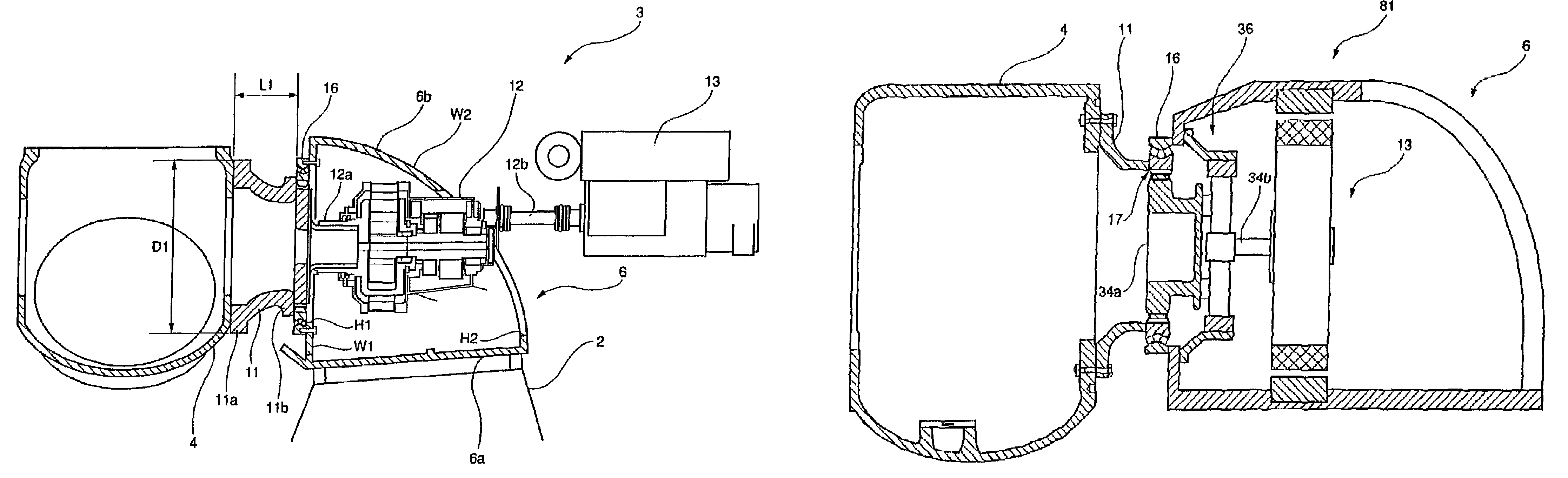
[0111]A second embodiment according to the present invention will be described below with reference to FIG. 4. A power generating wind turbine 31 of the present embodiment, as shown in FIG. 4, is partially different from the power generating wind turbine 1 of the first embodiment. In the power generating wind turbine 31 to be described below, parts and components same or similar to those of the power generating wind turbine 1 are designated by the same reference numerals and detailed description on the already described ones will be omitted.

[0112]The power generating wind turbine 31 of the present embodiment is mainly characterized in being different from the power generating wind turbine 1 in the shape of the main shaft, supporting structure of the main shaft and construction of the gear-box.

[0113]In the power generating wind turbine 31 shown in FIG. 4, as the main shaft to which the rotor head 4 is connected, a main shaft 32 having a minor axis is employed. Concretely, the main sh...

third embodiment

[0168]Next, a third embodiment according to the present invention will be described with reference to FIG. 12.

[0169]A power generating wind turbine 91 of the present embodiment, as shown in FIG. 12, is partially different from the power generating wind turbine 1 of the first embodiment. In the power generating wind turbine 91 to be described below, parts and components same or similar to those of the power generating wind turbine 1 are designated by the same reference numerals and detailed description on the already described ones will be omitted.

[0170]The power generating wind turbine 91 of the present embodiment is mainly characterized in being different from the power generating wind turbine 1 in the supporting structure of the main shaft. Concretely, in the power generating wind turbine 91, as the supporting structure supporting the main shaft 11, in place of the double-row tapered roller bearing 16, such a structure is employed that the main shaft 11 is supported to the nacelle...


PUM


Abstract

A power generating wind turbine includes parts and components installed in or on a nacelle which are made smaller and lighter, thus facilitating maintenance. A main shaft 11, a gear-box for speeding up rotation of the main shaft 11 and a generator 13 driven by an output of the gear-box 11 are provided on a nacelle bed plate 6. The main shaft 11 is connected to an input shaft 12a end of the gear-box 12 via a double-row tapered roller bearing 16. The main shaft 11 is supported to a wall portion W1 of the nacelle bed plate 6 with the double-row tapered roller bearing 16 being interposed therebetween. The main shaft 11 is formed in an annular shape having its outer diameter D1 larger than its axial directional length L1.

Description

TECHNICAL FIELD[0001]The present invention relates to a power generating wind turbine.BACKGROUND ART[0002]A power generating wind turbine comprises a nacelle installed on a tower, a wind turbine rotating blade, a gear-box inputted with a wind force received by the wind turbine rotating blade via a main shaft and a generator driven by an output of the gear-box. Such power generating wind turbine is known, for example, by Patent Documents 1 to 3 as mentioned below.[0003]In the Patent Document 1, for example, a power generating wind turbine is disclosed having a structure in which a rotor provided with a wind turbine rotating blade is directly installed on a planetary carrier of a gear-box to be supported to the gear-box.[0004]Also, in the Patent Document 2, a power generating wind turbine is disclosed having a structure in which a rotor hub is directly installed on a planetary holder to be supported to a gear-box.[0005]Further, in the Patent Document 3, a power generating wind turbine...

Claims


Application Information

Patent Timeline
Patent Type & Authority Patents(United States)
IPC IPC(8): F03D9/00H02P9/04F03D11/00F03D11/02F03D11/04F16C19/38F16C33/58F16C35/067F16H1/28
CPCF03D11/0008F03D11/02F16C19/386F16C2300/14Y02E10/726F16H57/082F16H2001/2881Y02E10/722Y02E10/725F16H37/041F03D80/70F03D15/00F16C2360/31F03D13/20F03D15/10Y02E10/72F03D9/00F16C19/22F16C19/38
Inventor SHIBATA, MASAAKIMIYAKE, HISAONUMAJIRI, TOMOHIROTOZAKI, YASUYOSHISHODA, KATSUHIKO
Owner MITSUBISHI HEAVY IND LTD
Why Eureka
Try Eureka