System and method for IDDQ measurement in system on a chip (SOC) design

a technology of integrated circuit and design, applied in the field of system and method for detecting transistor failure in, can solve the problems of increasing the probability of a fault in an integrated circuit, faulty parts of the integrated circuit must be first detected, and the probability of a failure in an integrated circuit may remain the same or decrease, so as to reduce the overall chip area needed, shorten the overall test time, and reduce the effect of overall chip area

Active Publication Date: 2007-10-16
TEXAS INSTR INC
View PDF2 Cites 77 Cited by
  • Summary
  • Abstract
  • Description
  • Claims
  • Application Information

AI Technical Summary

Benefits of technology

[0014]An advantage of a preferred embodiment of the present invention is that by maintaining constant power to the integrated circuit under test, test time is not spent having to wait for the integrated circuit to power down and then power up. Furthermore, a single set of test vectors can be scanned in for the entire integrated circuit and similarly, a single set of test results need to be scanned out. This results in a shorter overall test time for the integrated circuit. Therefore, more integrated circuits can be tested for a given amount of time and number of testing stations. However, should additional scan chains be desired, additional scan chains can be used.
[0015]A further advantage of a preferred embodiment of the present invention is that isolation buffers are not needed to isolate the individual power-domains. The elimination of the isolation buffers can reduce the overall chip area needed, resulting in a smaller integrated circuit.
[0016]Yet another advantage of a preferred embodiment of the present invention is that sub-power-domain IDDQ measurements can be made. This can allow for more accurate location of a faulty transistor, thereby allowing for easier replacement of the faulty device.

Problems solved by technology

As integrated circuits continue to increase in complexity and total number of devices, the probability of a failure may remain the same or decrease, but the probability of an integrated circuit containing a fault increases.
However, the faulty portions of the integrated circuit must first be detected.
One disadvantage of the prior art is the powering up, scanning in, and scanning out of each of the individual power domains can be time consuming.
This can reduce the number of integrated circuits that can be tested, perhaps resulting in the need for a large number of testing stations (which can be expensive) to meet production and testing demands.
A second disadvantage of the prior art is that logic isolation between the power domains is required.
Logic isolation adds more gates and can increase logic complexity as well as having a potentially adverse effect upon critical timing paths across power domains.
A third disadvantage of the prior art is that by testing individual power-domains, the individual power-domains need to be isolated from one another.
Yet another disadvantage of the prior art is that it prohibits the measurement of sub-power-domain IDDQ since internal VDD nodes are shorted together.
By not permitting sub-power-domain measurement of IDDQ, fine grained failed transistor testing is not possible, thereby reducing the ability to accurately locate a faulty transistor.

Method used


Image

  • System and method for IDDQ measurement in system on a chip (SOC) design
  • System and method for IDDQ measurement in system on a chip (SOC) design
  • System and method for IDDQ measurement in system on a chip (SOC) design

Examples


Embodiment Construction

[0034]The making and using of the presently preferred embodiments are discussed in detail below. It should be appreciated, however, that the present invention provides many applicable inventive concepts that can be embodied in a wide variety of specific contexts. The specific embodiments discussed are merely illustrative of specific ways to make and use the invention, and do not limit the scope of the invention.

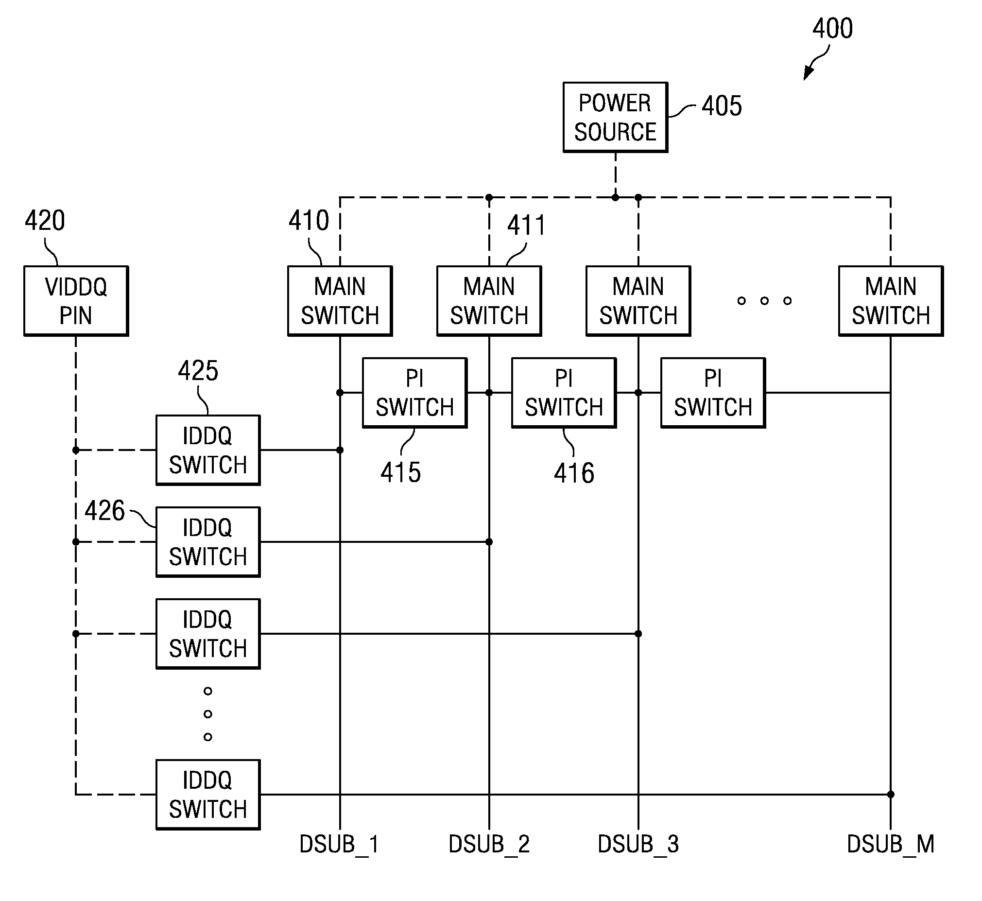
[0035]The present invention will be described with respect to preferred embodiments in a specific context, namely a system on a chip integrated circuit containing a large number of integrated circuits, with multiple power-domains. The invention may also be applied, however, to other integrated circuits with multiple power-domains, wherein there is a desire to rapidly test for faulty transistors by measuring IDDQ.

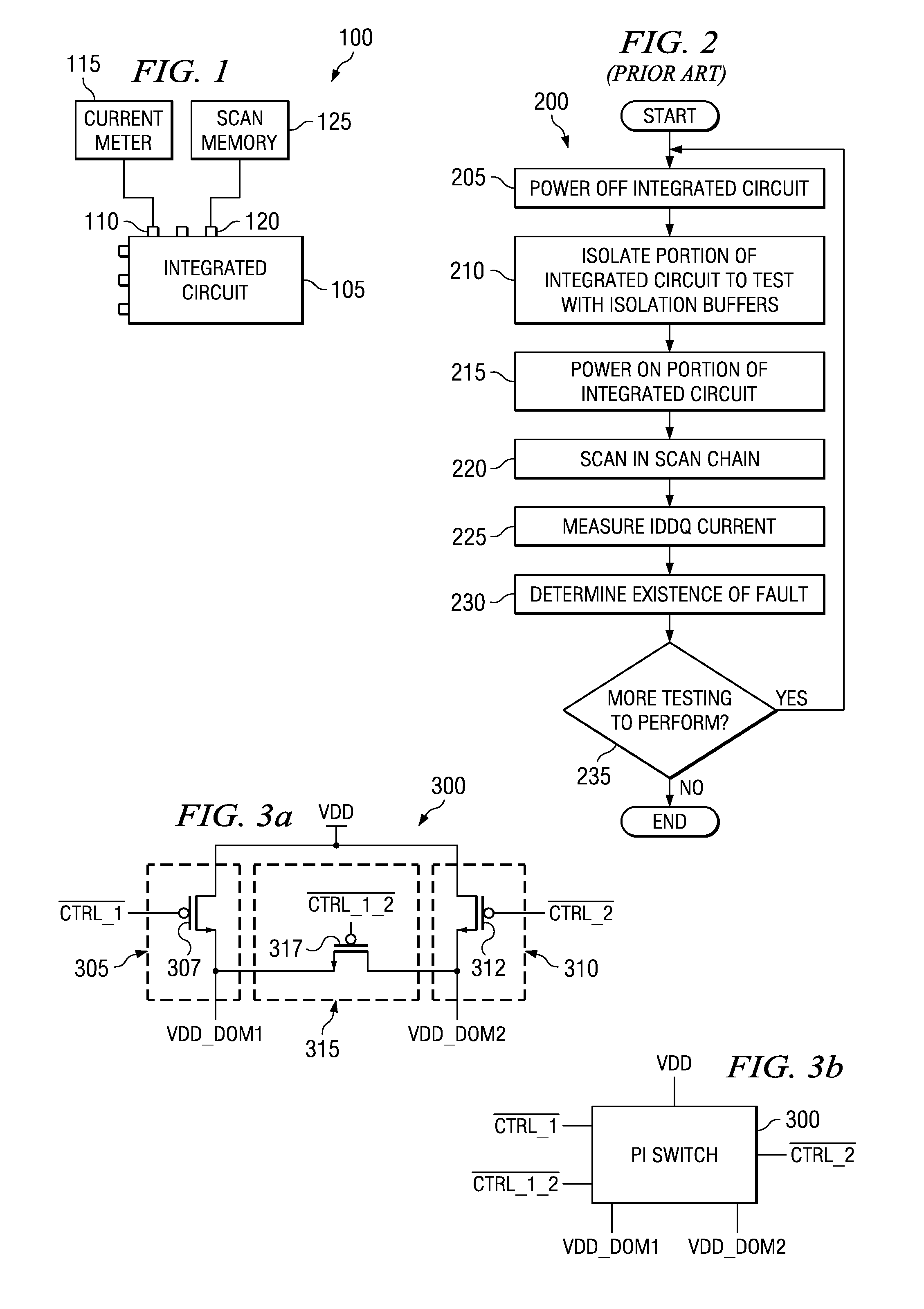
[0036]With reference now to FIG. 1, there is shown a diagram illustrating a test structure 100 for the testing of an integrated circuit 105 by measuring IDDQ currents...


PUM


Abstract

System and method for detecting transistor failure in large-scale integrated circuits by measuring IDDQ. A preferred embodiment comprises a switch structure for an integrated circuit made up of a plurality of main switches (such as main switch 410) selectively coupling a power sub-domain to a power source pin, a plurality of pi-switches (such as pi-switch 415) selectively coupling pairs of power sub-domains, and a plurality of IDDQ switches (such as IDDQ switch 425) selectively coupling the power sub-domains to a VIDDQ pin. The pi-switches can decouple the power sub-domains while the IDDQ switches can enable the measurement of the quiescent current in the power sub-domains. The use of pi-switches and IDDQ switches can permit the measurement of the quiescent current in the power sub-domains without requiring the use of isolation buffers and needed to powering on and off the integrated circuit between current measurements in the different power sub-domains.

Description

CROSS-REFERENCE TO RELATED APPLICATIONS[0001]This application is related to the following and commonly assigned patent applications: Ser. No. 10 / 735,943, now U.S. Pat. No. 7,180,208, filed Dec. 15, 2003, entitled “Switch Structure for Reduced Voltage Fluctuation in Power Domains and Sub-Domains,” which application is hereby incorporated herein by reference.TECHNICAL FIELD[0002]The present invention relates generally to a system and method for integrated circuit manufacturing, and more particularly to a system and method for detecting transistor failure in large-scale integrated circuits by measuring IDDQ.BACKGROUND[0003]As integrated circuits continue to increase in complexity and total number of devices, the probability of a failure may remain the same or decrease, but the probability of an integrated circuit containing a fault increases. In many integrated circuits, a certain degree of redundancy is built into the integrated circuit that will permit the faulty portions to be repla...

Claims


Application Information

Patent Timeline
Patent Type & Authority Patents(United States)
IPC IPC(8): G01R31/26
CPCG01R31/3012G01R31/3008
Inventor CHEN, WEIMAIR, HUGH T.KO, UMINGSCOTT, DAVID B.
Owner TEXAS INSTR INC
Why Eureka
Try Eureka