Time-variable magnetic fields generator and magnetic resonance apparatus embodying same

a generator and time-variable technology, applied in the direction of magnetic measurement, instruments, measurement devices, etc., can solve the problems of impaired efficiency of rf antennas, particularly the curve of rf fields, and achieve the effect of efficient gradient magnetic field generation, and efficient magnetic field generation

Inactive Publication Date: 2007-10-16
SIEMENS HEALTHCARE GMBH
View PDF12 Cites 10 Cited by
  • Summary
  • Abstract
  • Description
  • Claims
  • Application Information

AI Technical Summary

Benefits of technology

[0011]An advantage of the invention is that the conductor runs of the primary gradient coil unit do not necessarily have to occur connected as a coil winding in the central region; rather, a closure of coil windings can ensue outside of the central region over the connecting region. The generation of gradient magnetic fields is thereby more efficient since a return of the conductor can ensue at a greater distance, and thus the generation of magnetic fields that counteract the gradient magnetic field is reduced. The larger the connecting region, the more coil windings can be closed outside of the central region and the more efficient the generation of the gradient magnetic field. A further advantage is that the intervening space is used to form an RF antenna by means of the RF antenna elements. This enables a very compact design of the gradient coil unit and the RF antenna. Such a generator designed as a gradient coil radio frequency antenna unit exhibits a high degree of integration of gradient control unit and radio frequency antenna unit. High requirements of the gradient field can be fulfilled with one or more connection regions. The efficiency of the RF antenna, particularly the curve of the RF field, is impaired by the limitation of the antenna elements to the intervening spaces. The latter can, be compensated, for example, by stronger RF transmitters and contrast-improved MR measurement sequences.
[0012]The above object also is achieved by a magnetic resonance apparatus with at least one such generator. A larger examination region is available to the patient given the use of such a generator, in particular in open MR apparatuses.
[0013]For example, the magnetic resonance apparatus is based on a C-shaped permanent magnet with, for example, a vertical basic magnetic field. The basic magnetic field lies between two opposite pole plates and is optimally homogenous in the examination region of the magnetic resonance apparatus. If an inventive generator is arranged at each pole plate, a gradient magnetic field can be efficiently generated in the examination region.
[0014]In a particularly advantageous design of the generator, the regions of the primary gradient coil unit complement one another in an essentially plate-like manner, i.e. the regions lie in the same surface. The surface can thereby be planar or curved, adapted to the examination region.
[0015]In an embodiment of the generator, the central region is circular, the outer region is annular and the connecting region is fashioned like a spoke. This embodiment has the advantage that the geometry of the gradient control unit is particularly advantageously adapted to cylindrically symmetrical basic magnetic fields of C-arm-shaped magnetic resonance apparatuses. Alternatively, the regions can be fashioned as rectangles.
[0016]In a further embodiment of the generator, the gradient coil unit has a number of gradient coil conductors that can be fed with current individually or together. One of the gradient coil conductors runs from the outer region to the central region over a first of the connecting regions and back again to the outer region over a second of the connecting regions. Given the closure of the gradient coil windings, a section of a gradient conductor conducting a return current can be displaced radially outwardly in the outer region in this manner.

Problems solved by technology

The efficiency of the RF antenna, particularly the curve of the RF field, is impaired by the limitation of the antenna elements to the intervening spaces.

Method used


Image

  • Time-variable magnetic fields generator and magnetic resonance apparatus embodying same
  • Time-variable magnetic fields generator and magnetic resonance apparatus embodying same
  • Time-variable magnetic fields generator and magnetic resonance apparatus embodying same

Examples


Embodiment Construction

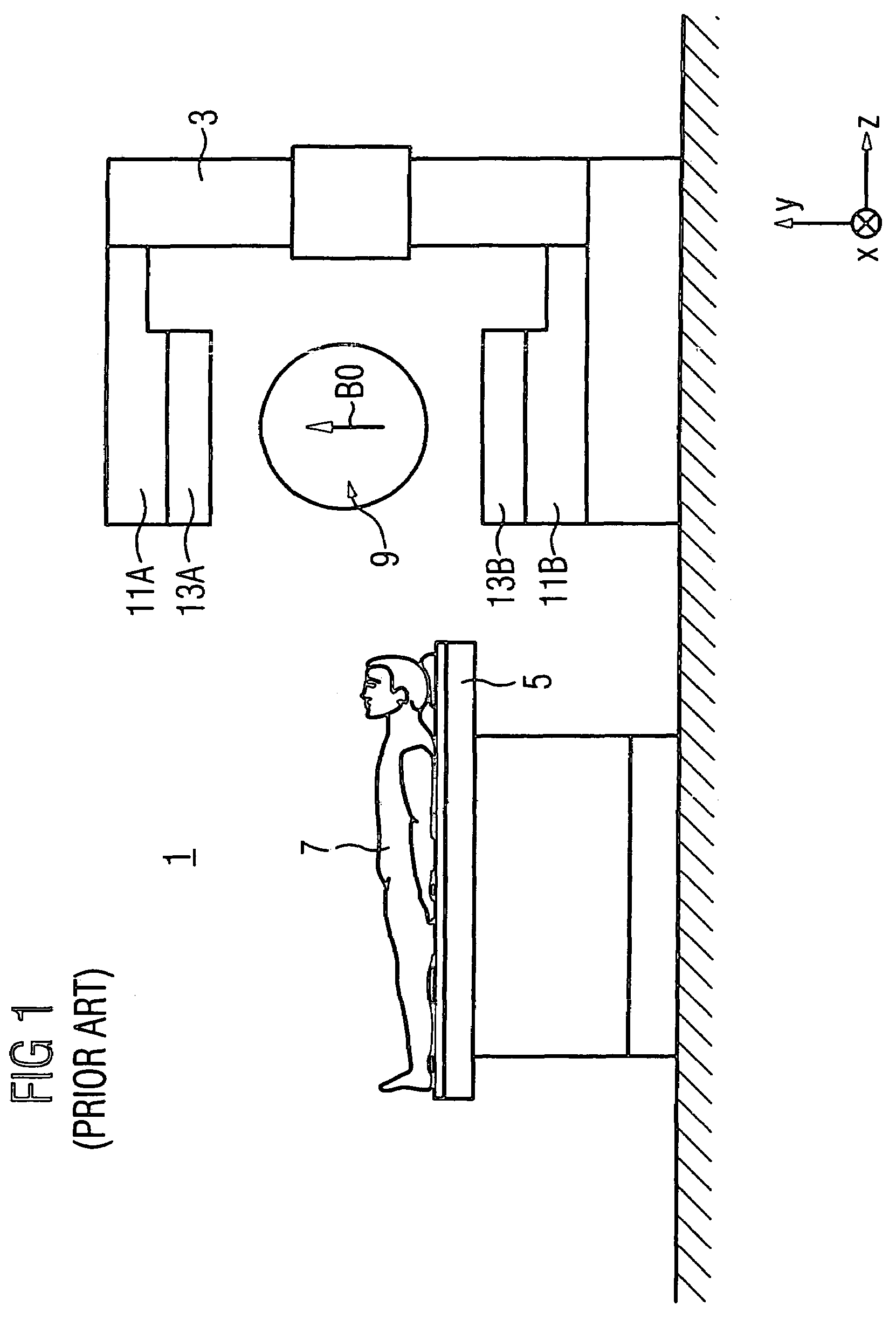
[0030]FIG. 1 schematically shows an open magnetic resonance apparatus 1 for medical examination of patients, for example by means of MR tomography or MR spectroscopy in a basic magnetic field B0 that is generated with a C-shaped basic field magnet 3. The temporally constant B0 field is generated in the y-direction corresponding to the specified coordinate system and, for example, is approximately 0.3 T. Furthermore, a patient bed 5 with which a patient 7 can be introduced into the examination region 9 is schematically shown.

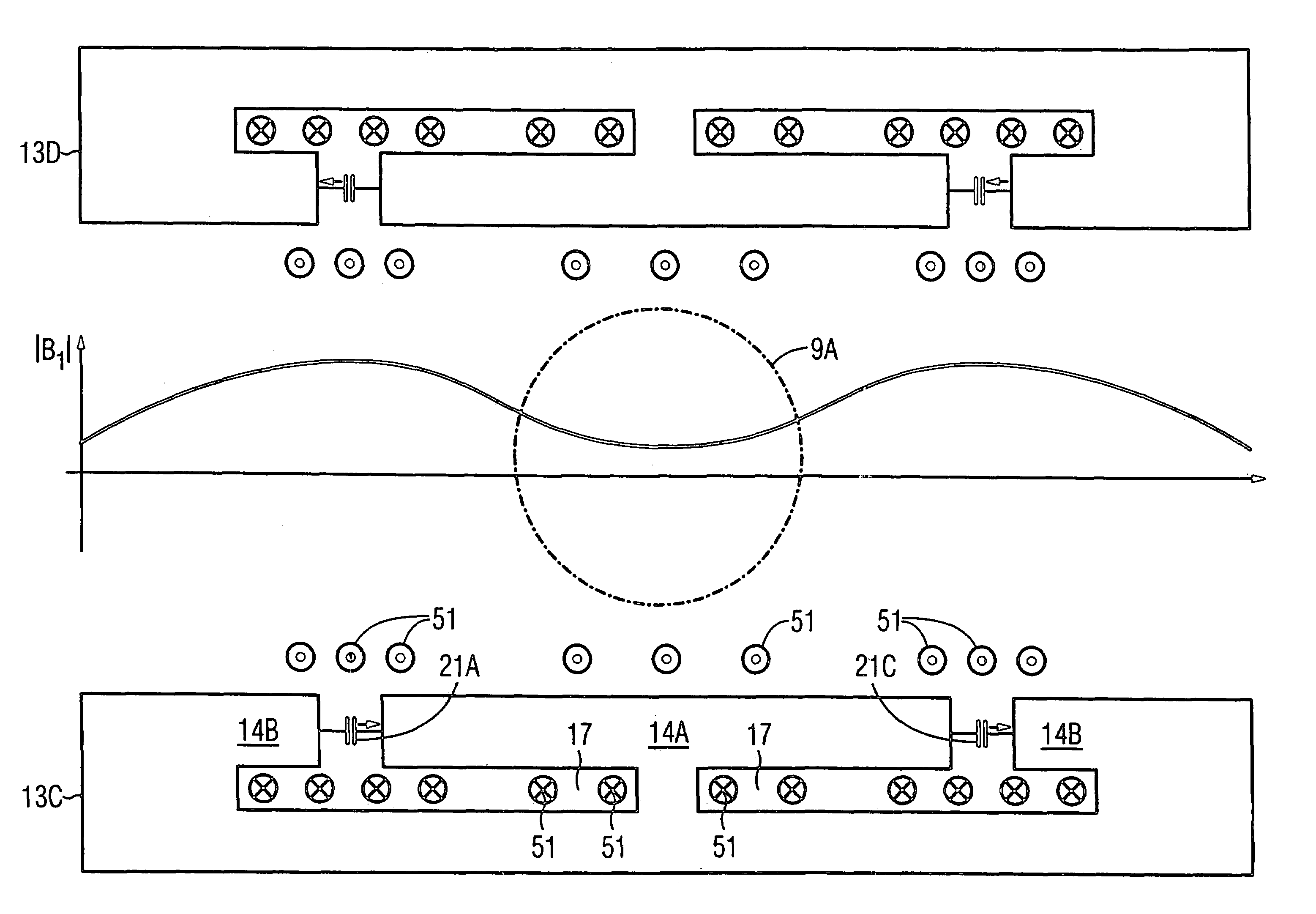
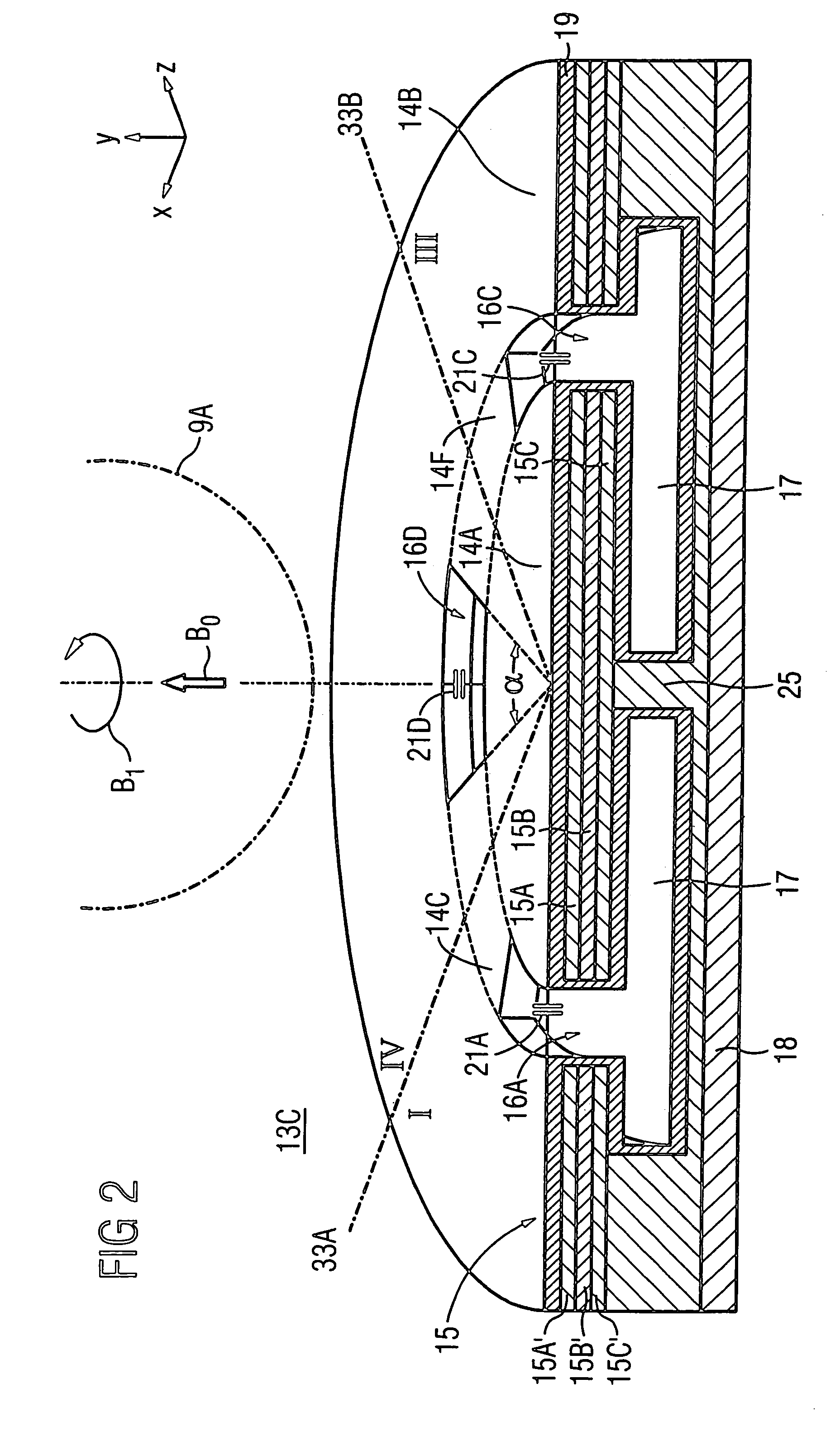
[0031]In the examination region 9, two time-variable magnetic fields generators 13A, 13B adapted to pole elements 11A, 11B of the basic field magnet 3 generate gradient fields and generate B1 radio frequency fields that are aligned perpendicular to the basic magnetic field B0. The generators 13A, 13B thus represent gradient coil units with integrated RF antenna units (gradient coil radio frequency antenna units) and enable a spatially resolved MR image acquisitio...


PUM


Abstract

A generator of time-variable magnetic fields generator for a magnetic resonance apparatus has a primary gradient coil unit for generating of a gradient magnetic field in an examination region of the magnetic resonance apparatus. The primary gradient coil unit, for accommodating at least one gradient coil conductor, has a central region, an outer region and at least one connecting region connecting the two regions. The outer region surrounds the central region. At least one intervening space is disposed between the central region and the outer region. The intervening space is free of the gradient coil conductors of the primary gradient coil unit and a radio frequency antenna element is disposed therein. Such a generator enables an effective gradient field and RF field generation in a compact design combining a gradient coil and a radio-frequency antenna.

Description

BACKGROUND OF THE INVENTION[0001]1. Field of the Invention[0002]The present invention concerns a time-variable magnetic fields generator with a primary gradient coil unit for generation of a gradient magnetic field in an examination region of a magnetic resonance apparatus. Furthermore, the invention concerns a magnetic resonance apparatus with at least one such generator.[0003]2. Description of the Prior Art[0004]Magnetic resonance technology is a known technology to, among other things, acquire images of the inside of a body of an examination subject. Rapidly switched gradient magnetic fields generated by gradient coils are superimposed on an existing static basic magnetic field B0 that is generated by a basic field magnet in an examination region of the magnetic resonance apparatus (MR apparatus). To excite magnetic resonance signals, the magnetic resonance apparatus also has a radio frequency antenna (RF antenna) that radiates RF signals (known as the B1 field) into the examinat...

Claims


Application Information

Patent Timeline
Patent Type & Authority Patents(United States)
IPC IPC(8): G01V3/00G01R33/34G01R33/385
CPCG01R33/385G01R33/34046
Inventor EBERLEIN, EVAGEBHARDT, MATTHIASRENZ, WOLFGANG
Owner SIEMENS HEALTHCARE GMBH
Why Eureka
Try Eureka